25
4.6 CONTROLS
It is recommended that all operators review this sec-
tion of the manual to familiarize themselves with the
location and function of all machine controls before
starting. Some machines may vary slightly due to
custom features but they are similar and all controls
are labelled.
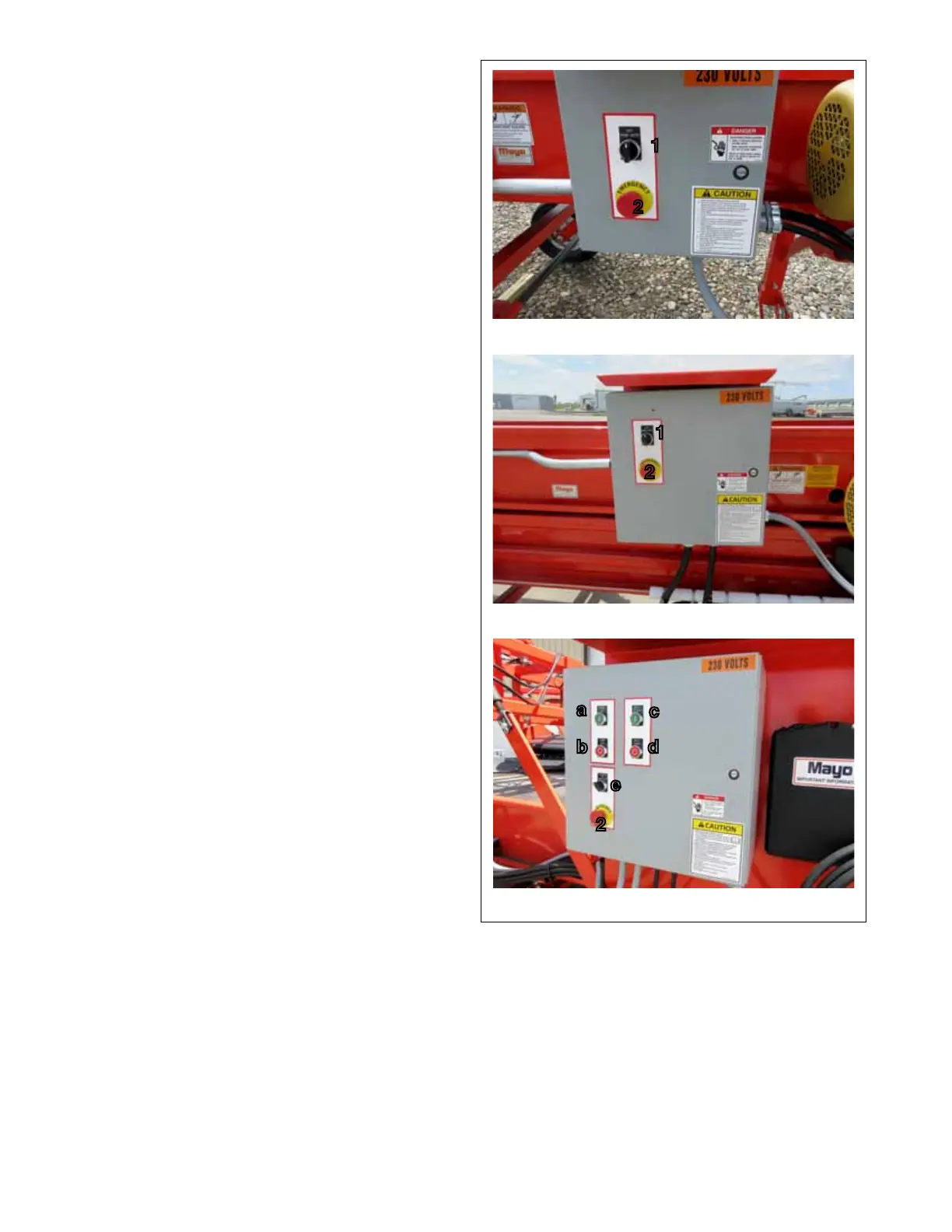
1. Operating Mode:
This 3 position rotary switch selects the operat-
ing mode. Turn the switch full counterclockwise to
operate in HAND or in the manual mode. Turn fully
clockwise to place in the AUTO mode when other
controls operate the system. Place in the center
position to turn OFF.
2. Emergency STOP:
This red push-pull switch is the master ON/OFF
switch on the panel itself and should be used as
an emergency shut down switch. Push the switch
in to turn all the power off. The switch will remain in
unless pulled out. It must be pulled out for any of
the other controls to work.
2. Optional Power Pack:
a. Pump ON.
This green push button switch controls the
power to the hydraulic pump. Depress to turn
pump ON.
b. Pump OFF:
This red push button switch controls the power
to the hydraulic pump. Depress to turn pump
OFF.
c. Belt Start:
This green push button switch controls the
power to the belt drive motor. Depress to turn
motor ON.
d. Belt Stop:
This red push button switch controls the power
to the belt drive motor. Depress to turn belt
OFF.
e. Stinger:
This three-position rotary switch selects the
Stinger operating mode. Turn the switch ful-
ly counterclockwise to operate in HAND or
manual mode. Turn fully clockwise to place in
AUTO mode when other controls operate the
system. Center switch to turn belt OFF.
Direct
Telescoping
FIG. 5 CONVEYOR CONTROLS (TYPICAL)
Optional Power Pack (Typical)
1
2
1
2
a
c
d
b
e
2