EasyManua.ls Logo

Maytag LAT8014 - Transmission Repair Procedure

Maytag LAT8014
184 pages
Print Icon
To Next Page IconTo Next Page
To Previous Page IconTo Previous Page
Loading...
______
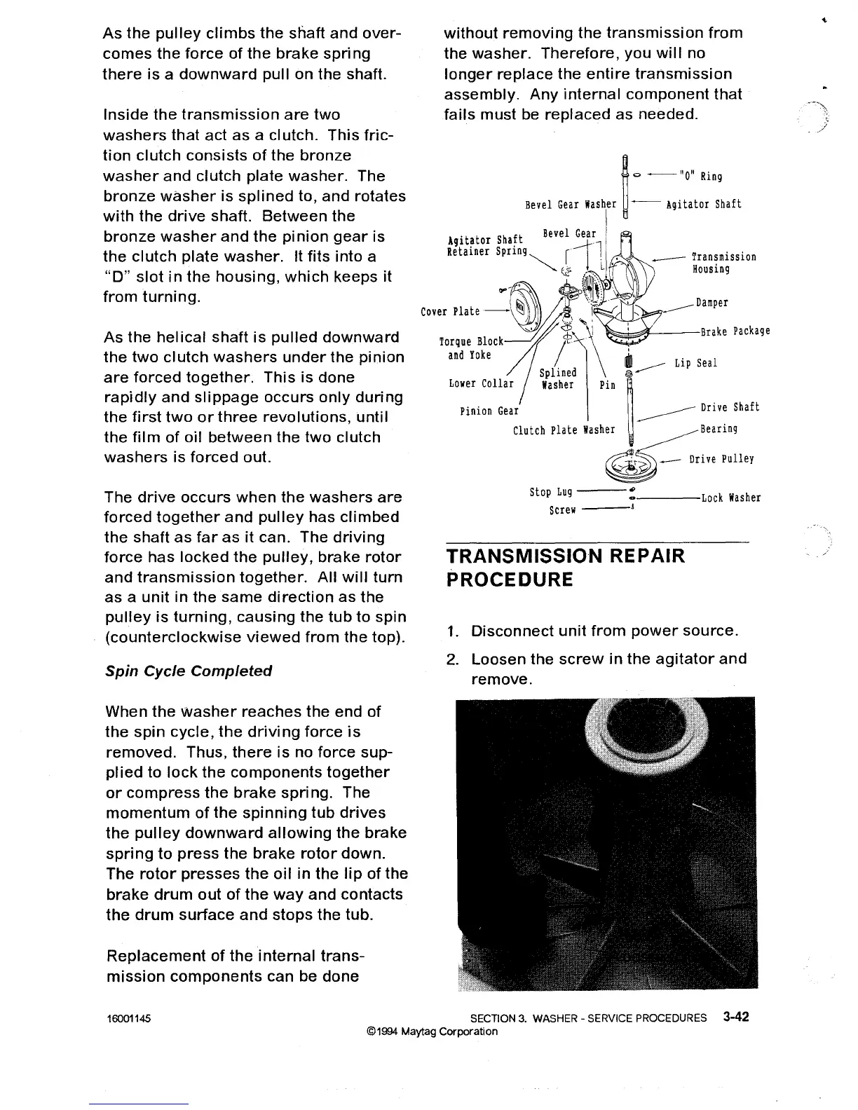
Transmission
Housing
without
removing
the
transmission
from
the
washer.
Therefore,
you
will
no
longer
replace
the
entire
transmission
assembly.
Any
internal
component
that
fails
must
be
replaced
as needed.
~
0
--
"0"
Ring
Bevel
Gear
Washer
~--
Agitator
Shaft
Agitator
Shaft
Bevel
Gear
Retainer
Spring~
rilL"
(,?
,-
....
~-~h;,I\,·
c
..
:,,,:~,,t:~~).
/:~
,~r
~~"...-_..----
__
D:::::
Package
and
Yoke
i'
______
Lip
Seal
Splined
~
Lower
Collar
lIasher
Pin
~
."",
G,,'
'
~
0"':
Sh,ft
Clutch
Plate
Washer
~Bearlng
~
Drive
Pulley
Inside
the
transmission
are
two
washers
that
act as a
clutch.
This
fric-
tion
clutch
consists
of
the
bronze
washer
and
clutch
plate
washer.
The
bronze
washer
is
splined
to,
and
rotates
with
the
drive
shaft.
Between
the
bronze
washer
and
the
pinion
gear
is
the
clutch
plate
washer.
It
fits
into
a
"D"
slot
in
the
housing,
which
keeps it
from
turning.
As
the
helical
shaft
is
pulled
downward
the
two
clutch
washers
under
the
pinion
are
forced
together.
This
is
done
rapidly
and
slippage
occurs
only
during
the
first
two
or
three
revolutions,
until
the
film
of
oil
between
the
two
clutch
washers
is
forced
out.
As
the
pulley
climbs
the
shaft
and
over-
comes
the
force
of
the
brake
spri
ng
there
is
a
downward
pull
on the shaft.
The
drive
occurs
when
the
washers
are
forced
together
and
pulley
has
climbed
the
shaft
as
far
as
it can. The
driving
force
has
locked
the
pulley,
brake
rotor
and
transmission
together.
All
will
turn
as
a
unit
in
the
same
direction
as
the
pulley
is
turning,
causing
the
tub
to
spin
(counterclockwise
viewed
from
the top).
Spin
Cycle
Completed
stop
Lug
---:----Lock
Washer
Screw
_--1
TRANSMISSION REPAIR
PROCEDURE
1.
Disconnect
unit
from
power
source.
2.
Loosen
the
screw
in
the
agitator
and
remove.
When
the
washer
reaches
the
end
of
the
spin
cycle,
the
driving
force
is
removed.
Thus,
there
is
no
force
sup-
plied
to
lock
the
components
together
or
compress
the
brake
spri
ng. The
momentum
of
the
spinning
tub
drives
the
pulley
downward
allowing
the
brake
spring
to
press
the
brake
rotor
down.
The
rotor
presses
the
oil
in
the
lip
of the
brake
drum
out
of
the
way
and
contacts
the
drum
surface
and
stops
the
tub.
Replacement
of
the
internal
trans-
mission
components
can be
done
16001145 SECTION
3.
WASHER - SERVICE PROCEDURES 3-42
©1994 Maytag
Corporation

Table of Contents