PAGE 14
FOR SERVICE TECHNICIAN’S USE ONLY
DO NOT REMOVE OR DESTROY
NOTE: On the gas dryer, the inlet thermistor is
located at the top of the drum inlet vent. Refer
to Strip Circuit on page 22 to diagnose heater
system.
Dryer does not heat:
Display flashes L2 (electric only):
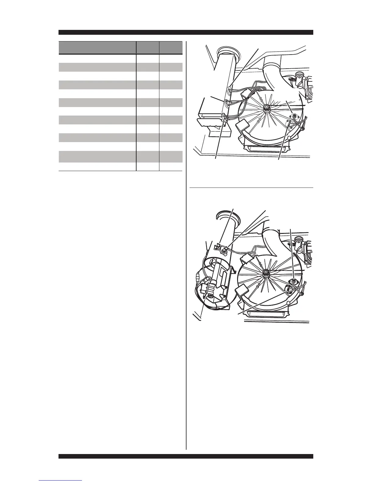
Locate the components using Figures 12a
and 12b.
ELECTRIC DRYER ONLY:
3Quick Check: Perform steps under “Install
Diagnostics”, page 5, to test for L1 and L2
line voltage.
•IfL1ispresent,theheaterrelayis
receiving L1 line voltage.
•IfL2ispresent,theheaterrelayis
receiving L2 line voltage, confirming that
the centrifugal switch, heater, high limit
thermostat, and the thermal cut-off are
functional.
1. Unplug dryer or disconnect power.
2. Remove front panel and drum assembly
to access thermal components.
3. Using an ohmmeter and referring to the Strip
Circuit or Wiring Diagram, measure the resistance
from the red wire terminal at the thermal cut-off
to the red wire terminal at the heater.
If the resistance is about 10 Ω, go to step 5.
If an open circuit is detected, or resistance
is much greater or less than 10 Ω, go to
step 4.
4. Visually check the wire connections to
the thermal cut-off, high limit thermostat, and
heater. If the connections look good, check for
continuity across each of these components.
Refer to Strip Circuit on page 22.
Replace the heater if it is electrically open.
Replace both the thermal cut-off and high
limit thermostat if either the thermal cut-off
or the high limit thermostat is electrically open.
 Loading...