Centrifugal Switch (Motor)
Gas Valve, Gas Dryer
Pluggable Drive Motor Switch
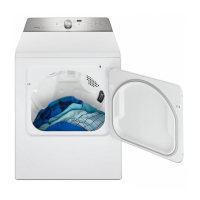
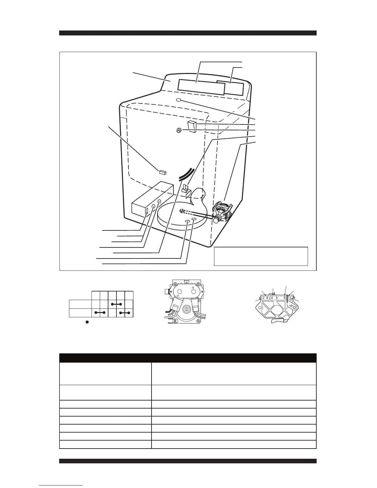
COMPONENT LOCATIONS
Remove top console to access:
•UserInterface(UI)
•CycleControlUnit(CCU)
Remove rear panel to access:
•InletThermistor(Gas)
•DrumLight
•WaterNozzle(SteamModel)
•WaterValve(SteamModel)
•MotorAssembly
& Belt Switch
Door Switch
(Location may vary
between models)
Remove front panel and drum
assembly to access:
•HeaterAssembly
•InletThermistor(Electric)
•HighLimitThermostat
•ThermalCut-off
•MoistureSensorStrips
•ThermalFuse
•OutletThermistor
Figure 17 - Component Locations.
SPECIFICATIONS
NOTE: Refer to Figure 12b, page 14,
for gas dryer component locations.
Top Console
Voltage:
240 V AC (200-260) Elect. Dryer, 2-phase, “optimized”
208 V AC (176-229) Elect. Dryer, 3-phase, “less optimized”
120 V AC (100-130) Gas Dryer
Amps:
(ELECT) 30 Amp Service
(GAS) 15 Amp Service
Frequency: 58 to 62 Hz (60 Hz nominal)
Water Pressure: 20-120 PSI
Operating Temperature Range: 40 to 105°F (5 to 40°C)
Dryer Height: 44 in. (112 cm)
Dryer Width: 29 in. (73.7 cm)
Dryer Depth: 29.5 in. (74.9 cm)
DRYER SPECIFICATIONS
 Loading...