5
Installation
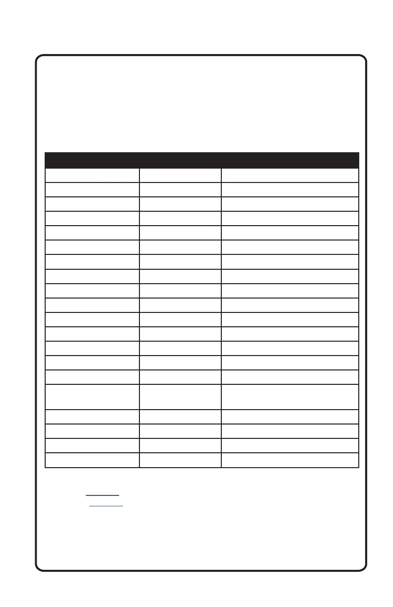
Wire Color/Tag Location Function
Black Power Plug Pin A Negative Chassis Ground (-)
Blue Power Plug Pin B Amp Turn-On (+12v Output)
Red Power Plug Pin J +12 volt Accessory
Yellow Power Plug Pin M +12 volt Constant
Orange / ILL Harness Illumination Control
Purple / Cam 2 Harness Camera 2 Trigger
Pink / Cam 1 Harness Camera 1 Trigger
Green / Subwoofer Harness Subwoofer Output Female-RCA
Gray / Zone 2 Harness Zone 2 Lineout Female-RCA
Brown / Zone 1 Harness Zone 1 Lineout Female-RCA
Black / Aux Harness Auxillary Input Female-RCA
Black / Mic Harness 3.5mm Phone Female Jack
Yellow / Video Out Harness Video Output
Yellow / Cam 2 / Red Harness Camera 2 Input Female-RCA
Yellow / Cam 1 / Wht Harness Camera 1 Input Female-RCA
* White/Orange
Aux Trigger
Harness Aux 1 – Aux 4 Trigger Output
Black / Antenna Harness Radio Antenna Input
Black / USB 1 Harness USB Input for Music
Black / USB 2 Harness USB Input for iPhone
** White/Orange RGB Harness RGB Output
Wiring and Connections
● We recommend wire-to-wire connections such as power, ground, and
speaker wiring are soldered and protected with either heat shrink
tubing or high quality electrical tape.
● The main (yellow) power wire should be connected to a source with
at least 10 amps of additional current capability to support the unit.
This has an in-line 5 amp fuse for protection.
Preamp Level Audio Connections
● Zone 1, Zone 2, and Subwoofer RCA preamp outputs are labeled as
such. These are intended to be connected to external amplifiers
(not included).
* Refer to Page 25 for aux trigger functionality.
** Refer to Page 26 for RGB output functionality.