10
Publication: ZTS-080812
M-B Companies, Inc. 11/15/12
INTRODUCTIONASSEMBLY
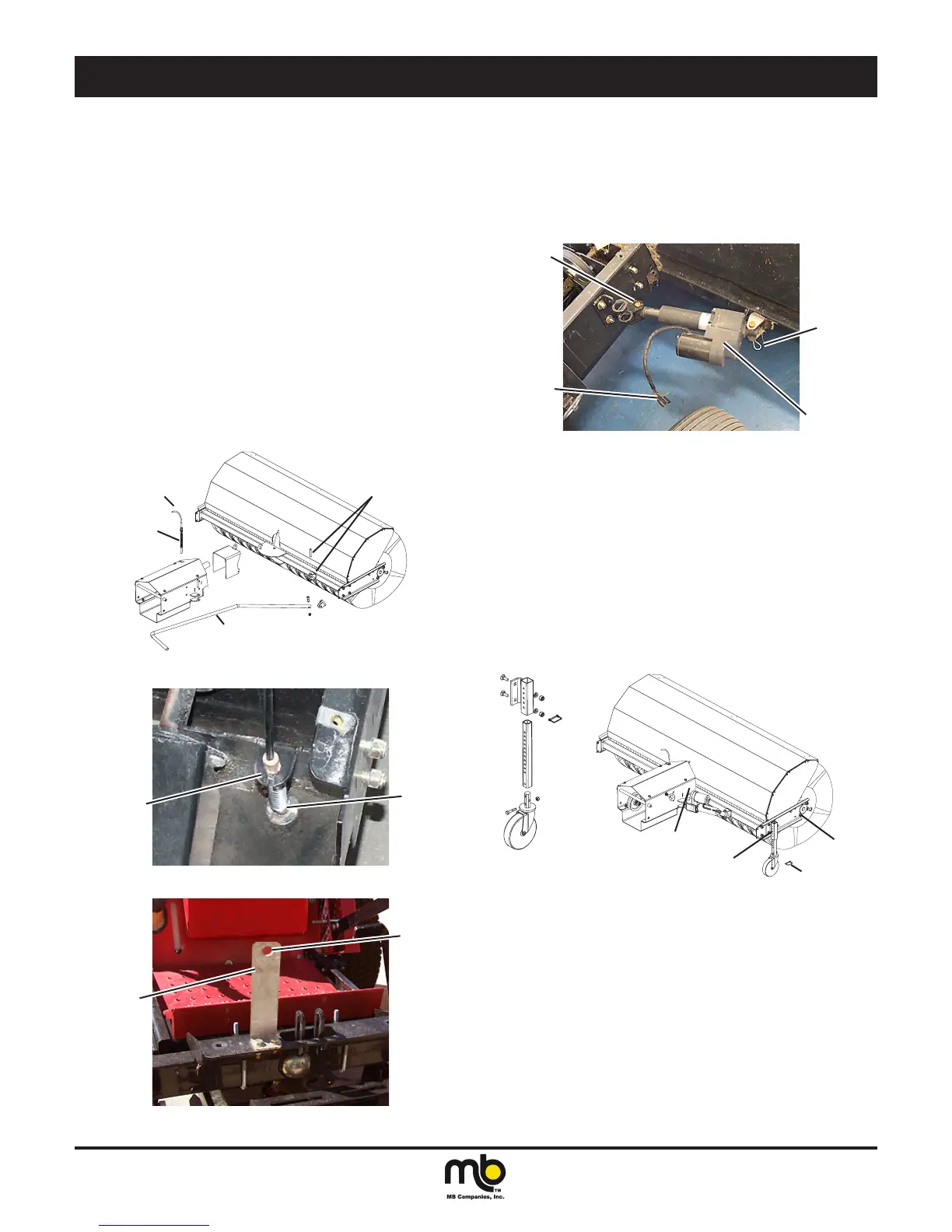
5. Swing Controls
Manual
If this tractor will be using the manual swing controls, assemble
the control cable for the release pin.
a. Remove the drive assembly cover. Compress the spring
against the shaft at the end of the cable. This will create a
gap between the spring and the end of the outer cover.
b. Insert the shaft into the guide bushing in the drive assembly.
c. Move the cable into the slot in the bracket. The gap created
by compressing the spring will allow the inner cable to move
through the slot. Releasing the spring.
d. Mount the bracket for the manual swing controls on the front
lift assist mount. Use two bolts with washers and nuts.
e. Route the control lever for the swing control through the
round hole on the bracket. Mount the hand lever on the
handlebar.
f. The swing control lever will go through the manual swing
bracket. The end at the broom head will have a swivel
assembly attached. Position the swivel assembly in the
bracket on the broom head. Insert the pin to secure it in
place.
Control Cable
F
A
Control Lever
Figure 8
C
B
Figure 9
D
E
Figure 10
Electric (Optional)
If this tractor will be using the electric actuator for swing
controls, mount the actuator.
a. Position the actuator as shown.
b. Insert one of the pivot pins and lock it in place with a clip.
c. Insert the second pivot pin and lock it in place with a clip.
d. Connect the electrical plug to the wiring harness from the
control box mounted to the handlebars.
A
C
D
B
Figure 11
6. Attach the casters.
a. Raise the attachment mount. The casters should already be
assembled. The illustration can be used to aid in assembly if
needed.
The caster mounting bracket can be mounted in any of three
positions:
Position 1 - Medium and heavy snow
Position 2 - Light to medium snow
Position 3 - Light snow and thatching
Attach a bracket on each side.
b. Slide the post into the bracket part way. Use the clip to hold it
in place. Repeat for the second caster. The height should be
the same for both casters.
Pin
1
2
3
Figure 12
The installation is complete. Refer to the Adjustments section for
broom pattern, attachment frame and V-belt adjustments.