3.7 Converter Power Wiring Diagram
The power supply line must be equipped with external surge protection for current overload (fuse or circuit breaker with
limiting capacity not greater than 10A). It must be easily accessible for the operator and clearly identied.
Power connection is made using the power terminal block on the upper right side of the terminal board.
NOTE: The terminal block unplugs from the circuit board for easy connection. Connect earth ground to the protective
grounding terminal before making other connections. The power supply of a standard converter is 100-240VAC, 45-66Hz
at maximum 20W. DC converter is available as an option.
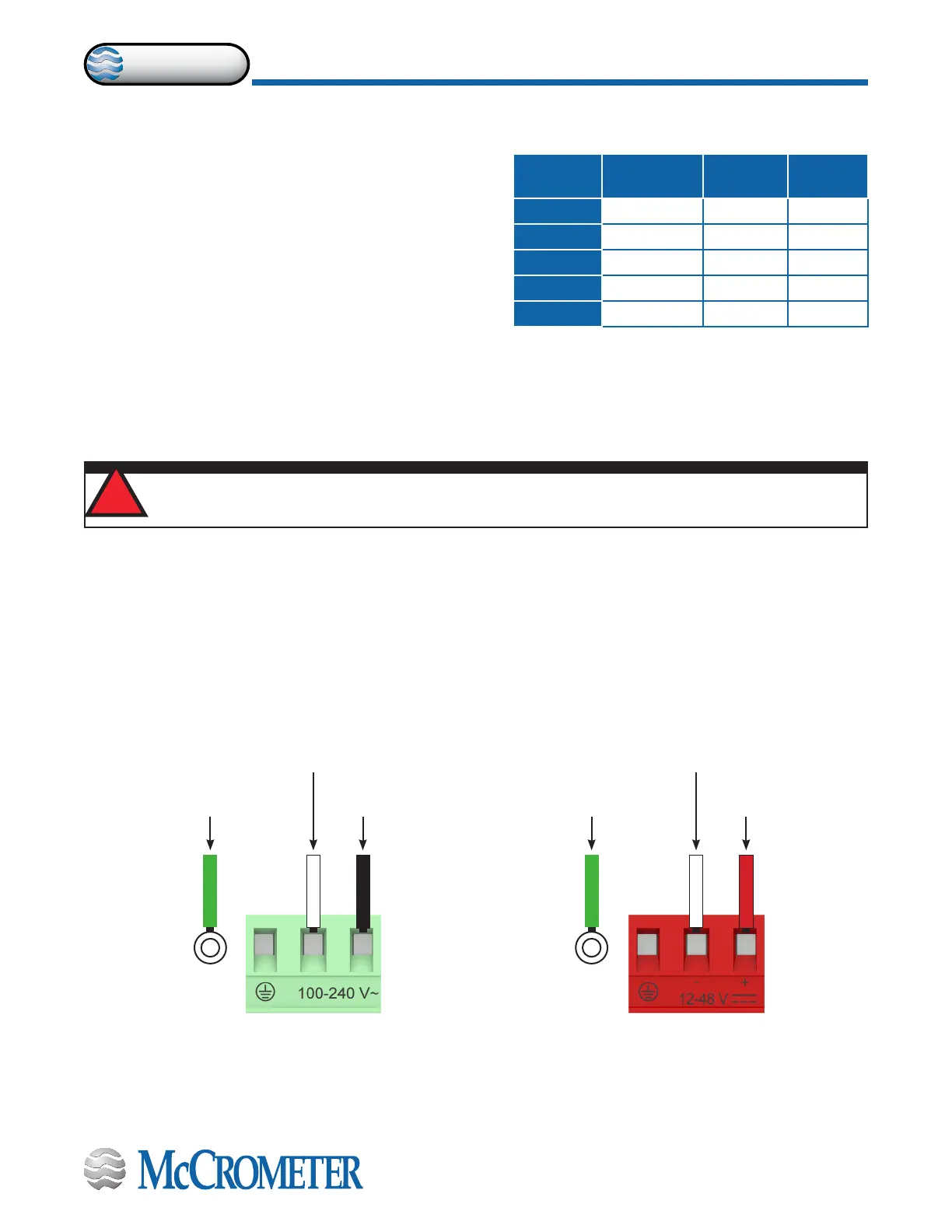
Figure 15. AC Power
Supply Terminal Block
Figure 16. Optional DC Power
Supply Terminal Block
WARNING!
Hazardous supply voltage can shock, burn, or cause death.
!
Neutral Wire
(typically a
white wire)
Power Supply
(typically a
white wire)
Ground Wire
(green or yellow/
green wire)
Ground Wire
(typically a
green wire)
Line Wire
(typically a black wire)
Power Supply +
(typically a red wire)
McCrometer AMR Interface Pinout
1
Power/Clock
2
Data
3
Ground
Badger Red Green Black
Elster Green Red Black
Itron Black Red Green
Neptune Black Red Green
Sensus Red Green Black
3.6 Optional Smart Output Hook Up
The convertor comes pre-wired with an interconnection
that should readily connect to most AMI transceivers. Where
interconnective devices are not mechanically compatible or
where non-standard wiring is encountered, the installer can
opt to remove the connector from the end of the converter’s
interface cable and make direct connection via the wiring table
shown at right.
• Signals and associated wire colors in the McCrometer
SmartOutput™ interface cable are identied together in
the top row of the table at right.
• Corresponding wire colors for transceivers from each
compatible AMI vendor are identied in the columns
under the top row.
30124-60 Rev. 1.2 | 16DEC2019
Page 11
CONNECTING WIRES TO TERMINALS