EasyManua.ls Logo

McCrometer ProComm User Manual

McCrometer ProComm
51 pages
To Next Page IconTo Next Page
Page #1 background imageLoading...
Page #1 background image
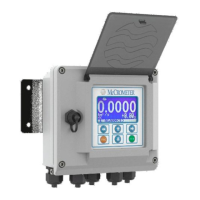
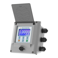
ProComm
Electromagnetic
Flow Meter Converter
30124-62 Rev. 1.0
unreleased
COMPONENT
NSF/ANSI/CAN 61
&
NSF/ANSI 372
®
I
A
P
M
O
R
&
T
ProComm
Installation, Operation and
Maintenance Manual
Preliminary
Date updated: 14 Jun 2019

Other manuals for McCrometer ProComm

Questions and Answers:

McCrometer ProComm Specifications

General IconGeneral
CategoryMedia Converter
ManufacturerMcCrometer
Ethernet Interface10/100Base-T
Power Supply12-24 VDC
Serial InterfaceRS-232, RS-485
Protocols SupportedModbus RTU, Modbus TCP
MountingDIN Rail

Summary

Safety Information

Key Safety Warnings

Provides crucial safety warnings related to installation, operation, and maintenance of the equipment.

Installing the Converter and Cables

Mounting the Converter

Details how to mount the remote mount converter to a solid surface or post using bolts or clamps.

Cable Gland and Conduit Installation

Explains how to route electrical cables through compression fittings or conduit, maintaining enclosure integrity.

Connecting Wires to Terminals

Terminal Block Diagram

Illustrates the terminal block layout for connecting wires to the converter for both remote and meter mount models.

Wiring Diagrams

Provides detailed wiring diagrams for different sensor types and power connections.

4-20mA Output Hook-Up

Explains how to connect isolated 4-20mA current loops for outputting flow data to external devices.

Converter Power Wiring

Shows wiring diagrams for both AC and optional DC power supply connections to the converter.

Converter Operation

Starting Up the Converter

Outlines the essential checks and procedures before powering up the converter for the first time.

Front Panel Display

Describes the different screens displayed on the converter's front panel and their associated flags.

Menu Structure

Details the hierarchical structure of the converter's menus, functions, and their corresponding codes.

Menu Descriptions

Menu 5 - Alarm Configuration

Details parameters for setting alarms based on maximum and minimum flow rate thresholds and hysteresis.

Menu 10 - Data Logger Setup

Explains how to enable and configure the data logger, including units, intervals, and event logging.

Error Codes

Alarm Messages

Troubleshooting Guide

Related product manuals