3.6 Converter Power Wiring Diagram
The power supply line must be equipped with external surge protection for current overload (fuse or circuit breaker with
limiting capacity not greater than 10A). It must be easily accessible for the operator and clearly identied.
Power connection is made using the power terminal block on the upper right side of the terminal board.
NOTE: The terminal block unplugs from the circuit board for easy connection. Connect earth ground to the protective
grounding terminal before making other connections. The power supply of a standard converter is 100-240VAC, 45-66Hz
at maximum 20W. DC converter is available as an option.
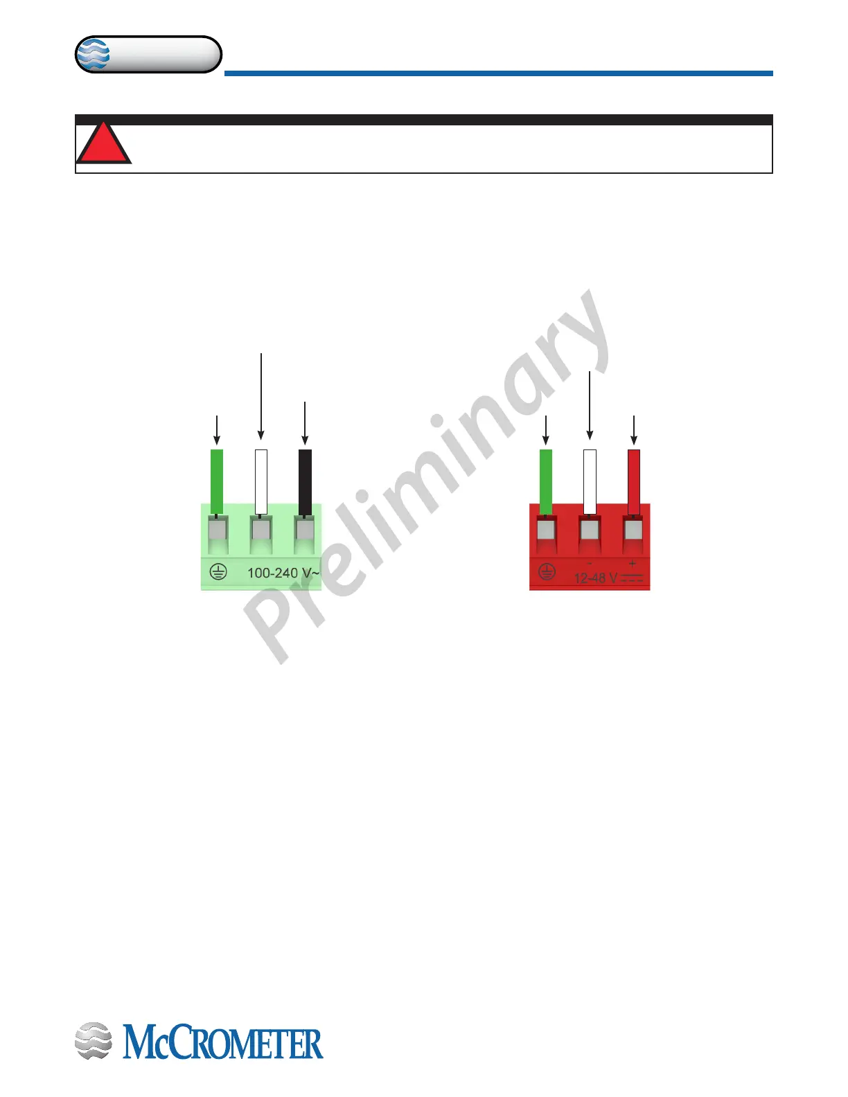
Figure 15. AC Power
Supply Terminal Block
Figure 16. Optional DC Power
Supply Terminal Block
WARNING!
Hazardous supply voltage can shock, burn, or cause death.
!
Neutral Wire
(typically a white wire)
Power Supply -
(typically a white wire)
Ground Wire
(green or
yellow/green wire)
Ground Wire
(typically a green wire)
Line Wire
(typically a black wire)
Power Supply +
(typically a red wire)
30124-60 Rev. 1.0 | unreleased
Page 11
CONNECTING WIRES TO TERMINALS
ProComm