1.0 CONVERTER DESCRIPTION
Read this entire manual prior to installation and/or changing any settings. Retain this manual in your records, DO NOT
DISCARD.
The signal converter is the reporting, input and output control device for the sensor. The converter allows the measurements,
functional programming, control of the sensor and data recording to be communicated through the display and inputs
& outputs. The microprocessor-based signal converter has a multi-point curve-tting algorithm to improve accuracy,
dual 4-20mA analog outputs, an RS485 communication port, an 8-line graphical backlit LCD display with six-key touch
programming, and a rugged enclosure that meets IP67. In addition to a menu-driven self-diagnostic test mode, the
microprocessor continually monitors the converter's functionality. The converter will output rate of ow and total volume.
The converter also comes standard with password protection and many more features.
2.0 INSTALLING THE CONVERTER AND CABLES
2.1 Verify Serial Numbers
The converter and sensor are supplied as a matched system. Verify the meter serial numbers on both the converter and
sensor match. This will ensure a properly calibrated system.
The tag on the side of the converter has the converter model Number, the converter serial number, the converter model
number and the sensor model number. An example is shown below as Figure 1.
Figure 1. Converter Serial Number Tag
IMPORTANT: Verify the meter serial numbers on both the converter and sensor match. This will ensure
a properly calibrated system. The meter serial number is located on the side of the sensor, and the
converter serial number and the meter serial number are located on a label on the side of the converter.
Ensure the meter serial number on the sensor and the converter tags match.
i
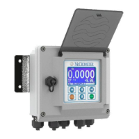
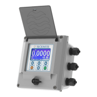
Meter mount converter Remote mount converter
30124-60 Rev. 1.0 | unreleased
Page 2
CONVERTER DESCRIPTION
ProComm