2.3 Installing Cables through Cable Glands and Conduit
All electrical cables enter the converter through compression ttings or optional customer-supplied conduit located on the
side or bottom of the converter (Figure 5, Figure 6, Figure 7) . Ensure that all compression glands are properly tightened and
all unused ttings are plugged so the case remains sealed.
The power cable and wiring harnesses are each assigned specic cable glands where they will pass through into the
converter. See section 2.4 for cable gland assignment for wiring harnesses and section 3.2 for wiring diagrams.
All cable compression glands must be properly tightened to prevent moisture intrusion and maintain the IP67 rating. To
insure IP67 rating, use only round cable 0.24" to 0.47" in diameter.
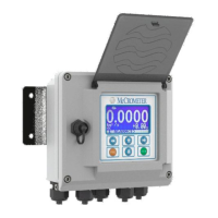
Figure 5. Remote mount
converter with ve cable
gland pass-throughs
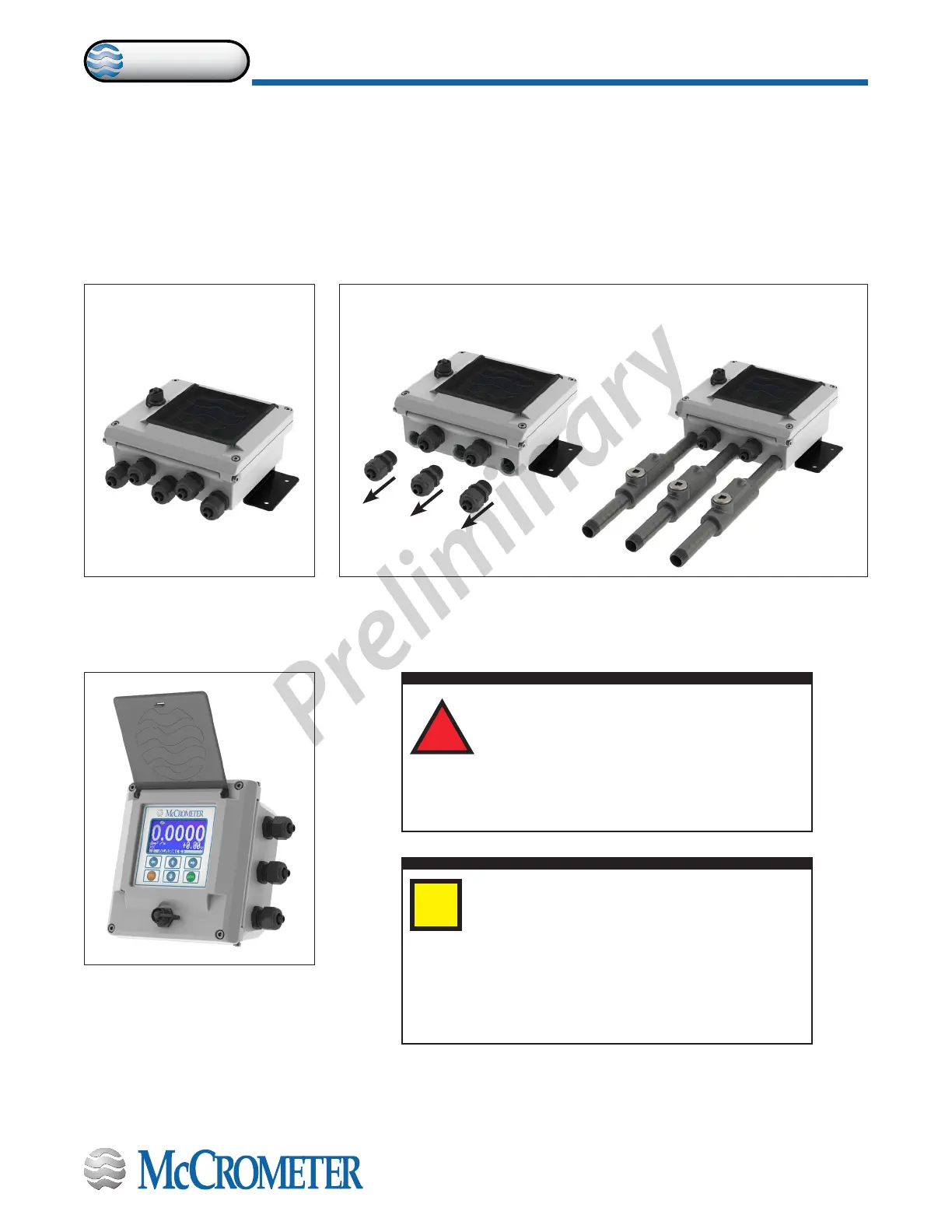
Figure 6. Remote mount converter
with three conduit pass-throughs
The remote mount converter is shipped with ve 1/2" NPT cable glands.
Up to three cable glands may be removed and replaced with 1/2" conduits.
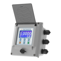
Figure 7. Meter mount
converter with three cable
gland pass-throughs
IMPORTANT: Do not cut or alter the cable
length on power or signal cables!
Connections to the sensor must be made with
cable supplied by McCrometer specically for
that purpose. Do not substitute the supplied cable with
other types of cable, even for short runs. For repairs or
added lengths of cable, the entire cable between the sensor
and the converter must be replaced. (Consult factory for
replacement cable.)
i
!
Attaching conduit directly to the enclosure may
introduce dangerous gasses and moisture into
the enclosure creating a dangerous condition,
and will remove the enclosure's IP67 rating.
Damage caused by attaching conduit to the enclosure or
altering the enclosure in any way is not covered by the
warranty.
30124-60 Rev. 1.0 | unreleased
Page 4
INSTALLING THE CONVERTER AND CABLES
ProComm