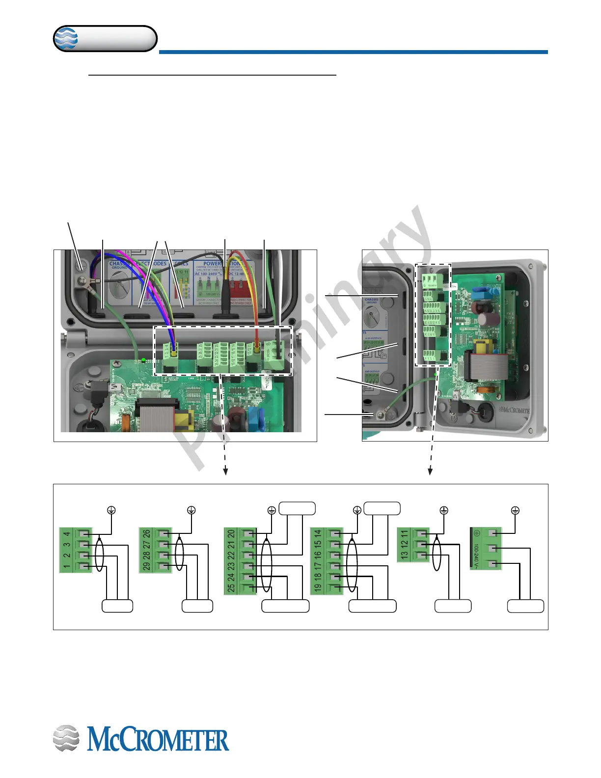
Figure 11. Terminal Block Diagram
D2 D1 DC
RS485 4-20 OUTPUTS
+24VVC
DIGITAL OUTPUTS
IN1+
DIGITAL INPUTS
IN1 -
C1
COILS
C2 L(+) N(-)
POWER SUPPLYELECTRODES
E1 E2 C
B A VC
AO2 AO1 AOC
Meter mount viewRemote mount view
3.0 CONNECTING WIRES TO TERMINALS
3.1 Terminal Block Diagram
All connections are made on the terminal blocks. To access the terminal blocks, loosen the four screws on the front of
the converter and open the front panel. Refer to Figure 6 and Figure 7. The example shown below (Figure 11) does not
necessarily represent all converter models, however, it shows the placement for all terminal blocks used in all models.
NOTE: The terminal blocks unplug from the circuit board for easy connection.
Chassis
lug
Outputs
Power
Electrodes
Chassis lug
Outputs
Coils and
ground
Power
30124-60 Rev. 1.0 | unreleased
Page 7
CONNECTING WIRES TO TERMINALS
ProComm