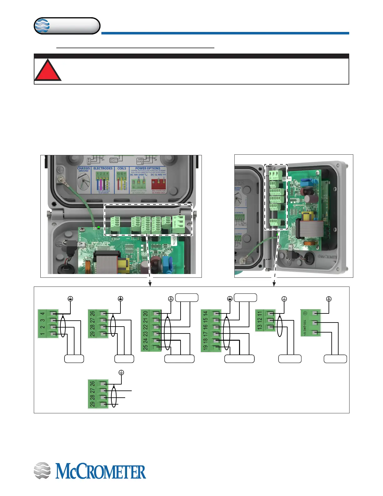
Figure 11. Terminal Block Diagram
E1 E2 C
B A VC
AO2 AO1 AOC
D2 D1 DC C1 C2
L(+) N(-)
RS485 4-20 OUTPUTS
DIGITAL OUTPUTS
DIGITAL INPUTS
COILS POWER SUPPLYELECTRODES
AMI OUTPUT
DATA
CLOCK
GROUND
+24VVC
IN1+ IN1 -
Meter mount viewRemote mount view
3.0 CONNECTING WIRES TO TERMINALS
3.1 Terminal Block Diagram
All connections are made on the terminal blocks. To access the terminal blocks, loosen the four screws on the front of
the converter and open the front panel. Refer to Figure 6 and Figure 7. The example shown below (Figure 11) does not
necessarily represent all converter models, however, it shows the placement for all terminal blocks used in all models.
NOTE: The terminal blocks unplug from the circuit board for easy connection.
!
WARNING!
Ensure device is disconnected or circuit breaker is open per the requirements of IEC 60947-1 and IEC 60947-3
before opening the opening the converter.
30124-60 Rev. 1.2 | 16DEC2019
Page 7
CONNECTING WIRES TO TERMINALS