SmarTraq
6 Manual # 42-02-D008 Rev. A2
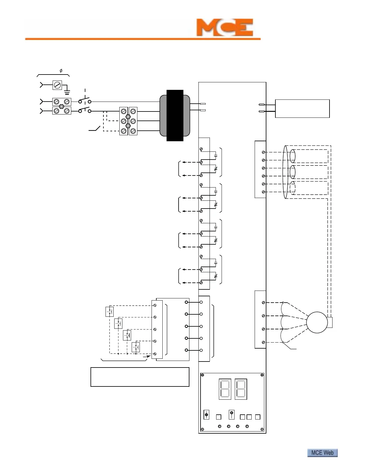
Figure 3. SmarTraq Wiring Diagram
CLOSED LOOP DOOR
SMARTRAQ LIMITLESS
Connect inputs
to the Isolation
board. NEVER
CONNECT
THESE INPUTS
DIRECTLY TO
THE MAIN
(BOTTOM)
CIRCUIT BOARD.
1
2
3
4
TB-2
1
TB-3
R-CLAMP
IN -B
(white)
(black)
5
6
9
7
8
+S
-S
-E
ENC1
ENC0
SOUT
MOTOR
V
U
W
N
DOOR
14 AWG
OPERATOR
OVER VOLTAGE
PROTECTION UNIT
-
+
ENTER NUDGE REMOTE
LOCAL OPEN
CLOSE
ONBOARD PROGRAMMER
12
11 DOL
6
5
LIMIT 2
TB-4
YELLOW/GREEN
RED
BLUE
BLACK
WHITE
GREEN
10
4
DOOR OPEN
LIMIT OUTPUT
TO CONTROLLER
TO CONTROLLER
(if used)
LIMIT 2 OUTPUT
9
7
8
LIMIT 1 OUTPUT
TO CONTROLLER
(if used)
3
2
1
LIMIT 1
(LP)
(LC)
TO CONTROLLER
LIMIT OUTPUT
DOOR CLOSE
DCL
Off/On Switch
(Circuit Breaker)
GND
208VAC
Voltage
Select
Wire
120VAC
240VAC
0V
28V
Main
Transformer
L1
L2
G
AC In
120/208/240VAC,
50/60Hz, 1
SHIPPED FROM FACTORY
WIRED FOR 120VAC Input
WARNING:
DO NOT APPLY VOLTAGE TO THIS CIRCUIT.
PROVIDE DRY CONTACTS ONLY.
INPUTS
ISOLATION BOARD
9
10
7
8
3
J6
Motor power and encoder
factory-wired for complete
operator installations.
NOTE: If compliance to ASME A17.1-1996 (Rule 210.15),
ASME A17.1-2000/CSA B44-00 (Requirement 2.26.5), or
CSA B44-94 (Requirement 3.12.1.5) is required, you must
provide a door position monitoring switch.
Connect the switch as shown in the elevator control
drawings package.
DOOR
OPEN
DOOR CLOSE
NUDGING
HEAVY DOOR
28VAC (From Pin 10)
User provides relays / wiring
Motor and encoder
leads may be run in
the same conduit.