Installation
5
All door operators must have FULL OPEN and FULL CLOSE bumpers.
Otis 6970 Door Operators: When removing the Otis motor, access to the lower bolt is
through the inspection cover on the front of the gear case:
• Remove the inspection cover.
• Rotate the gear so one of the large holes exposes the lower bolt.
• Be careful not to drop the bolt or the lock washer in the gear case.
• Oil checks need to be adjusted for minimal effect. However, do not completely back out
existing oil check adjustments.
Otis OVL (11.33:1): Special instructions required. Please reference MCE #42-IS-0224.
OVL kit is for Otis OVL with gear ratio of 11.33:1 ONLY.
4. Unless the existing belt is in like-new condition, replace it with a robust, grip-type belt
with notches.
5. Adjust belt tension. (Closed-loop control requires minimal belt elasticity, slack, or slip-
page.)
6. Adjust all chains and cables for minimal slack.
7. Mount the inverter drive enclosure in a location that allows the provided 8-foot (2.5
meter) encoder cable to easily reach from the motor to the enclosure. (Coil any excess
cable length inside the drive enclosure. Avoid trimming the encoder cable.)
If the encoder cable is trimmed, an unused brown wire will be exposed. Do not use the brown
wire. Note that the original yellow/green wire was soldered to the cable shield. If removed, it
must be replaced and connected as shown in the wiring diagram.
8. Check that the drive On/Off switch is set to OFF. Connect the encoder cable and power
wires from the motor to the drive as shown in the wiring diagram.
9. Make connections between the drive and the elevator controller as shown in the wiring
diagram. Motor and encoder leads may be run in the same conduit.
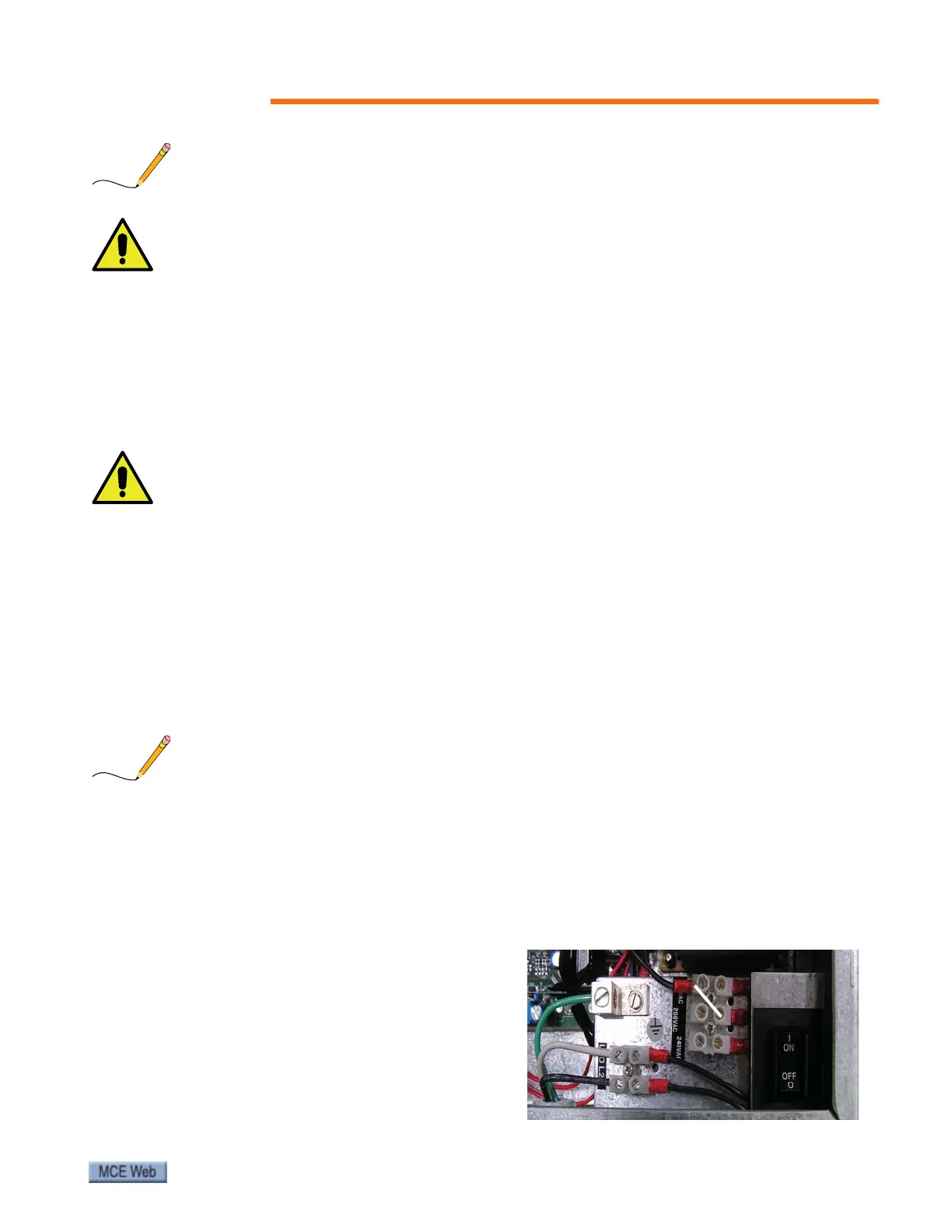
10. The drive is factory- configured for
120VAC power.To configure for 208 or
240VAC power, move the input select
wire. Please refer to “SmarTraq Wiring
Diagram” on page 6 and information on
page 13. Refer to the controller job prints
for other wiring.