Installation
13
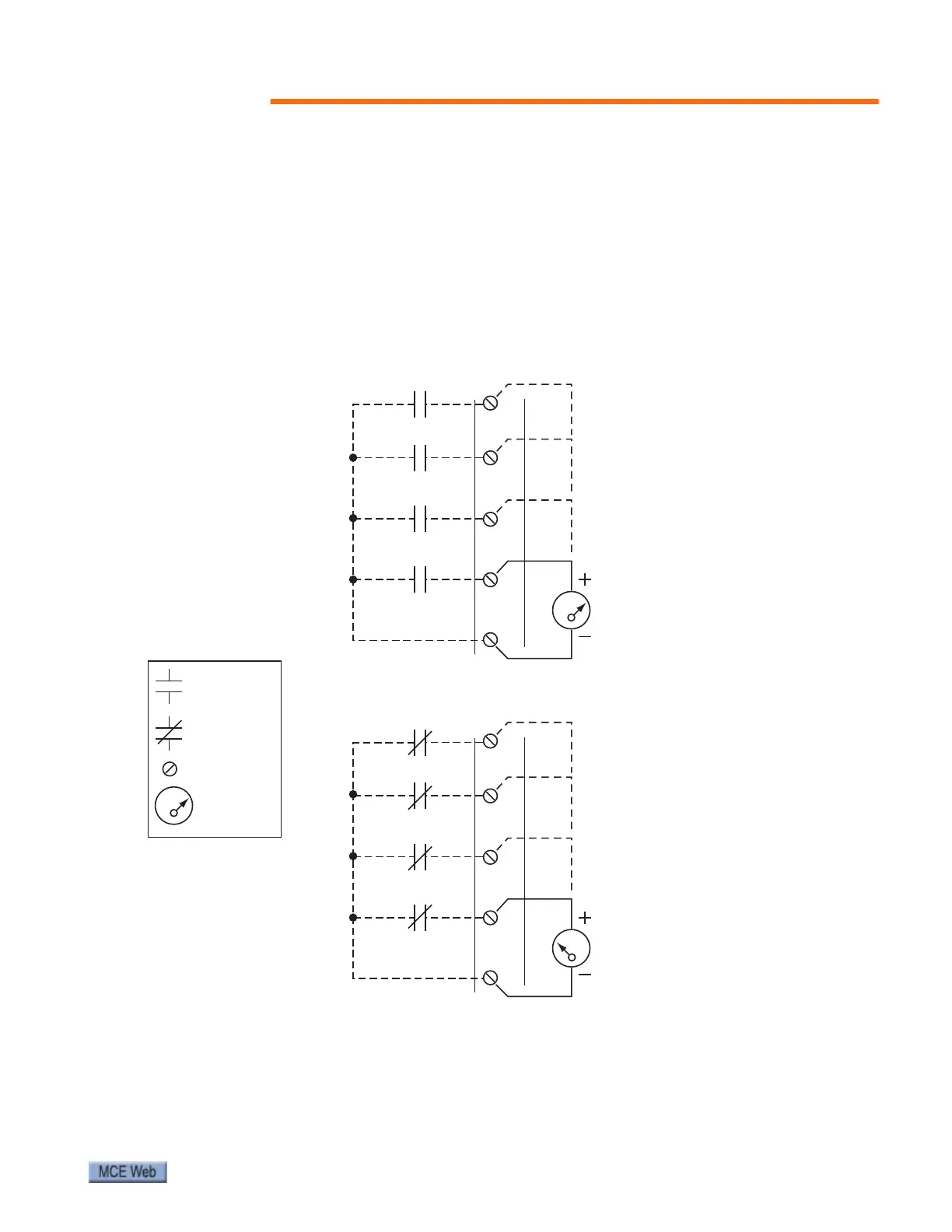
Referring to the SmarTraq wiring diagram, page 6, and to the following verification drawing,
note that, when closed, the dry contact closures provide a connection between the associated
control input (HD, ND, DC, or DO) and terminal 10 on the J6 connector. These connections
should be detailed on the job prints supplied by the controller manufacturer. However, espe-
cially when upgrading or retrofitting, you may have to provide relays or reuse existing relays to
provide these contact closures.
The illustration below provides an example of how to use a voltmeter to test the state (open/
closed) of the dry contacts.
Figure 5. Verifying Contact States at J6 Door Control Inputs
Open Contact
Voltmeter
Closed Contact
Terminal
KEY:
7
3
8
9
10
ND (NUDGING)
DC (DOOR CLOSE)
HD (HEAVY DOOR)
DO (DOOR OPEN)
J6
24 Volts AC
(black)
(red)
0 Volts AC
(black)
(red)
Measuring voltage across
a closed contact to Terminal 10
Measuring voltage across
an open contact to Terminal 10
7
3
8
9
10
ND (NUDGING)
DC (DOOR CLOSE)
HD (HEAVY DOOR)
DO (DOOR OPEN)
J6