24 24
Setup
How to Operate the Setup Modes
Your McIntosh C1000 has been factory configured for de-
fault operating settings that will allow immediately enjoy-
ment of superb audio without the need for further adjust-
ments. If you wish to make changes to the factory default
settings, a Setup Feature is provided to customize the oper-
ating settings using the Front Panel Alphanumeric Display
on the C1000C Controller. The setup fuctions available for
change and/or adjustments are dependent upon connection
of the Preamplifier(s) connected to the C1000C Controller,
C1000P, C1000T or both.
1. The Red LED above the STANDBY/ON push-button
lights to indicate the C1000 is in Standby mode and is
connected to a live AC Outlet. To switch On the
C1000, press the STANDBY/ON push-button. Refer
to figure 2. The Alphanumeric Display will indicate the
last input listened to. If this is the first time the C1000
is switched on, the display will indicate “15 TUNER”,
refer to figure 3a. If both Preamplifiers (C1000P and
C1000T) are connected to the same C1000 Controller
the display will indicate “15 TUNER1”, refer to fig-
ure 3b.
Notes: 1.
Dependent upon which Preamplifier
(C1000P and/or C1000T) is connected to the
C1000C, the Front Panel Alphanumeric
Display will indicate different operational
messages when switched On, refer to page 42
for additional information. If the Front Panel
Alphanumeric Display indicates CABLE
ERROR, refer to figure 4, remove the AC Power
Cord from the Rear Panel of the C1000C. Then
check to verify that both interconnect cables
Figure 3a
Figure 7
Figure 6
Figure 5
Figure 4
coming from the C1000P and/or C1000T are
connected to the correct sockets on the Rear
Panel of the C1000C. Refer to page 12 for the
C1000P, refer to page 14 for the C1000T or
refer to page 16 for the C1000P and C1000T
combination. After correcting the cable
connection error, reconnect the AC Power Cord
to the Rear Panel of the C1000C. Perform Step
one again.
2. When both Preamplifiers (C1000P and C1000T)
are connected to the same C1000 Controller,
the C1000P Preamplifier default Input Title
names will have a number 1 added to the end of
the Title. Refer to figure 3b. The C1000T
Preamplifer default Input Title names will have
a number 2 added to the end of the Title. Refer
to
figure
3c.
3. There is no Input Title
“D/A2” available when both Preamplifiers
(C1000P and C1000T) are connected to the
same C1000 Controller, the McIntosh
MDA1000 may be connected to either
preamplifier.
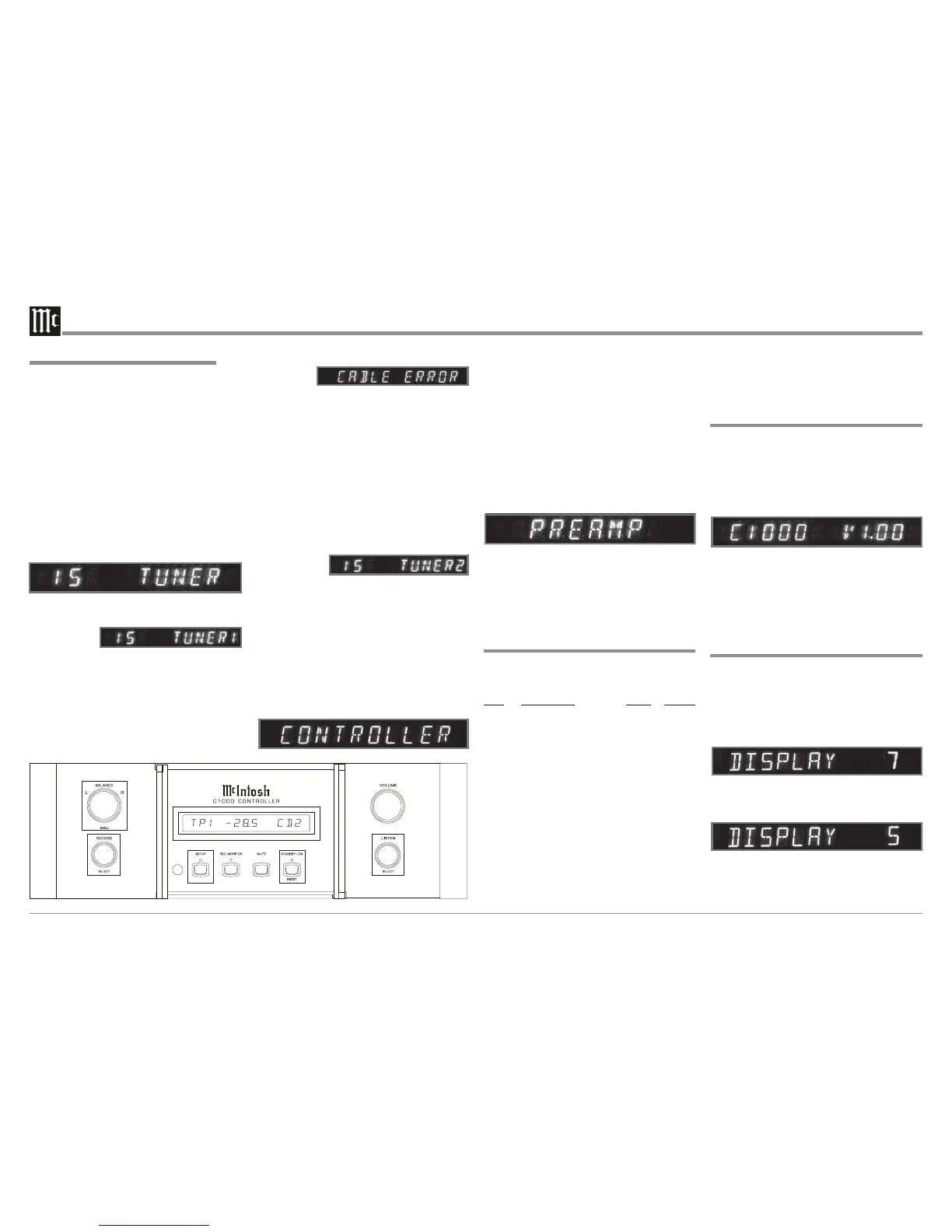
2. Press the C1000C Front Panel SETUP push-button
once. The LED above the SETUP Push-button will il-
luminate and the Front Panel Display will indicate
CONTROLLER. The “Controller” is the first of the
two main menus. The second main menu is named
“Preamp” and will be accessed in step 5. Refer to fig-
ures 2 and 5.
The following listings indicate the Setup Menu Mode
(Controller or Preamp), Menu Name, Default Setting and
the page number for instructions on how to change a set-
ting.
Default Settings
Menu Function Name Setting Page No.
Control Version (C1000 Firmware) _ . _ _ 24
Control Display (Brightness) 7 24
Control Meter (Illumination) ON 25
Control Volume (Display) Precent 25
Control Trigger A (Rear Panel Jack) 5Volt 25
Control Trigger B (Rear Panel Jack) 5Volt 25
Control Triamp (Balanced Outputs) OFF 26
Control D/A Control (MDA1000) OFF 26
Preamp Input 3 (Title of Inputs) TUN 27
Preamp D Port (Assignment to Input) Note 2 28
Preamp Trim (Input Source Level) 00 28
Preamp Trigger (Input Source) -- 29
Preamp ACC Control (Remote Con.) -- 29
Preamp LPROC (Listen Processor) NONE 30
Preamp RPROC (Record Processor) NONE 31
Preamp MM (Phono Capacitance) 50PF 32
Preamp MC (Phono Resistance) 25OHM 32
Preamp Passthru (Multichannel) Off 32
Notes: 1. Charts on page 33 and 34 allow for recording
3. Rotate the BALANCE (Menu) Control and notice that
the Setup Controller Setup Mode advances through
seven different possible adjustment selections and one
informational display.
Note: When in SETUP MODE, it may be necessary to
rotate the Controls (BALANCE, RECORD and
LISTEN) either clockwise or counter-clockwise to
the desired function or setting.
4. Press the SETUP Push-button to exit the CONTROL-
LER Menu, the LED above the SETUP Push-button
will extinguish and the Front Panel Display will revert
back to its normal display. Refer to figure 3.
5. Now Press the SETUP Push-button twice to enter the
PREAMP Setup Menu. Refer to figure 6.
6. Rotate the BALANCE (Menu) Control and notice that
the Setup Preamp Mode advances through nine differ-
ent possible adjustment selections.
7. To exit from the Setup Preamp Mode press the SETUP
Push-button, the LED above the SETUP Push-button
will extinguish and the Front Panel Display will revert
back to its normal display. Refer to figure 3a or 3b.
Display Brightness
The Front Panel Alphanumeric DISPLAY Brightness may
be varied from a setting of 1 (Dim) to 7 (Bright). Follow
the steps below for reducing the Display Brightness.
1. Press the SETUP Push-button once to access the Setup
Controller Mode unless the C1000C is already in the
Setup Controller Mode.
2. Rotate the BALANCE (Menu) Control until the word
“DISPLAY 7” appears. Refer to figure 8.
3. Rotate the LISTEN (Select) Control until the Front
Panel Alphanumeric Display indicates “DISPLAY 5”
or the desired Brightness is achived. Refer to figure 9.
4. If no other adjustments are to be made at this time,
press the SETUP Push-button to exit the Setup Con-
troller Mode or proceed to the next desired Setup Con-
troller Mode for adjustment.
Figure 9
Firmware Version
The C1000 functionality is controlled by internal software
that is know as Firmware. The Version of the Firmware in
the C1000 can be identified at any time by utilizing the
Setup Controller Mode.
1. Press the SETUP Push-button once to access the Setup
Controller Mode.
2. Rotate the BALANCE (Menu) Control until VER-
SION 1.0 or higher appears. Refer to figure 7.
3. The number after the character V is the Firmware
number.
4. If no other adjustments are to be made at this time,
press the SETUP Push-button to exit the Setup Con-
troller Mode or proceed to the next desired Setup Con-
troller Mode for adjustment.
Figure 8
Figure 2
any changes made to the default settings.
2. The D. Port default assignment is the same as the
C1000 Controller Rear Panel Data Port
Labeling.
Figure 3b
Figure 3c
 Loading...