8 8
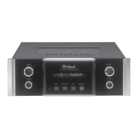
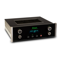
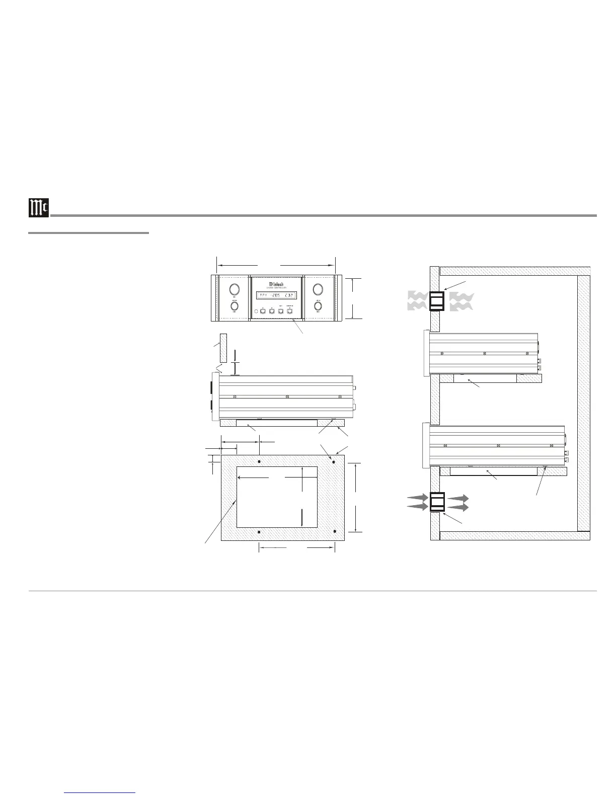
The C1000C, C1000P and C1000T can be placed
upright on a table or shelf, standing on their four
feet. The four feet, may be removed from the bot-
tom of the C1000C, C1000P and C1000T when
they are custom installed as outlined below. The
four feet, together with the mounting screws should
be retained for possible future use if the C1000C,
C1000P and C1000T are removed from the custom
installation and used free standing. They also can be
custom installed in a piece of furniture or cabinet of
your choice. The required panel cutout, ventilation
cutout and unit dimensions are shown.
Always provide adequate ventilation for the
C1000C, C1000P and C1000T. Cool operation en-
sures the longest possible operating life for any
electronic instrument. Do not install the units di-
rectly above a heat generating component such as a
high powered amplifier. If all the components are
installed in a single cabinet, a quiet running ventila-
tion fan can be a definite asset in maintaining all the
system components at the coolest possible operating
temperature.
A custom cabinet installation should provide the
following minimum spacing dimensions for cool
operation. Allow at least 2 inches (5.08 cm) above
the top of the C1000C, C1000P and C1000T, 2
inches (5.08cm) below the bottom and 1 inch (2.54
cm) on each side of the Controller/Preamplifier, so
that airflow is not obstructed. Allow 24 inches
(61.0cm) depth behind the front panel
1
for Intercon-
nect Cables. Allow 1 inch (2.54 cm) in front of the
mounting panel for clearance. When the C1000C,
C1000P and C1000T are to be installed in custom
cabinets refer to illustrations to the right. Be sure to
cut out a ventilation hole in the mounting shelf ac-
cording to the dimensions in the drawing.
1
Interconnect Cables are supplied with the C1000P
and C1000T Preamplifiers and connect to the
C1000C Controller.
Installation
Installation
 Loading...