11
11
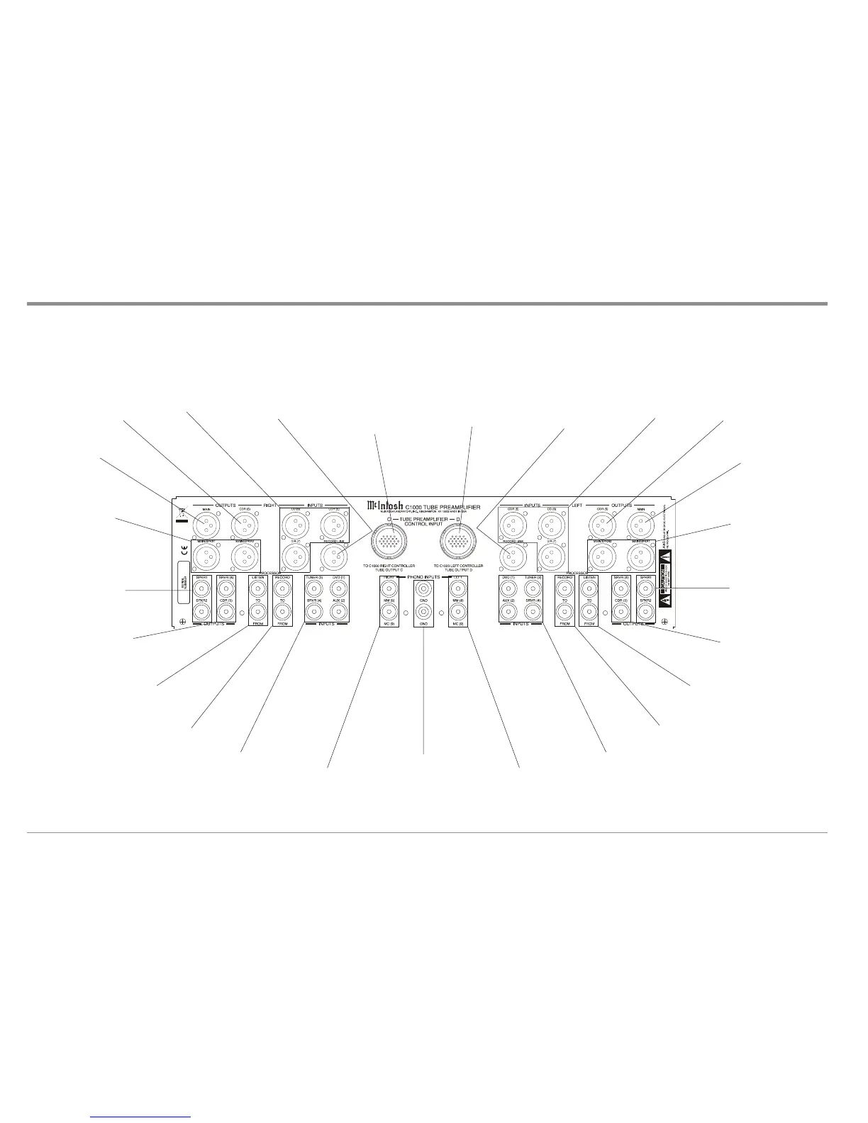
C1000 Tube Preamplifier Rear Panel Connections
MAIN RIGHT Channel
OUTPUTS (Balanced)
contain Listen program
signals at all times
MAIN/SPKR 1 and 2 RIGHT
Channel OUTPUTS (Bal-
anced) contain Listen signals
and may be assigned either as
two additional Main Outputs
(active all the time) or
switched On/Off with the Re-
mote Control SPKR 1 and 2
Push-buttons
PROCESSOR RIGHT Channel LISTEN
TO and FROM allow an external signal
processor to be connected for use in the
Listen mode
PROCESSOR RIGHT Channel RECORD
TO and FROM allow an external signal
processor to be connected for use in the
Record mode
CD (6), CDR (5) and
D/A (7) RIGHT
Channel INPUTS
(Balanced) accept
high level program
source signals
TUNER (3), DVD (1), SRVR (4)
and AUX (2), RIGHT Channel
INPUTS (un-balanced) accept
high level program source signals
PHONO INPUTS RIGHT MM (8)
accepts signals from a Moving
Magnet Phono Cartridge. MC (9)
Input accepts the low level signals
from a Moving Coil Phono Car-
tridge
SPKR 1 and 2 RIGHT Channel
OUTPUTS (unbalanced) contain
Listen signals and are switched
On/Off with the Remote Control
SPKR 1 and 2 Push-buttons
RECORD LINK INPUTS (Bal-
anced) connect to the Record Link
RIGHT Channel Input on the
C1000P Preamplifier when the
C1000T and a C1000P Preamplifi-
ers are both connected to the same
C1000C Controller, allowing for
the sharing of their inputs for re-
cording purposes
CDR (5) RIGHT
Channel OUPTUTS
(Balanced) contain
the selected Record
Source Signal for
recorders
SRVR (4) and CDR (5) RIGHT
Channel OUPTUTS (Unbalanced)
contain the selected Record Source
Signal for recorders
GND (Ground)
connectors for
connecting the
Turntable
Ground Wire to
the C1000T
Chassis
RECORD LINK INPUTS (Bal-
anced) connects to the Record Link
LEFT Channel Input on the
C1000P Preamplifier when the
C1000T and a C1000P Preamplifi-
ers are both connected to the same
C1000C Controller, allowing for
the sharing of their inputs for re-
cording purposes
CD (6), CDR (5) and
D/A (7) LEFT Chan-
nel INPUTS (Bal-
anced) accept high
level program source
signals
CDR (5) LEFT
Channel OUPTUTS
(Balanced) contain
the selected Record
Source Signal for
recorders
MAIN LEFT Channel
OUTPUTS (Balanced)
contain Listen program
signals at all times
MAIN/SPKR 1 and 2 LEFT
Channel OUTPUTS (Bal-
anced) contain Listen signals
and may be assigned either as
two additional Main Outputs
(active all the time) or
switched On/Off with the Re-
mote Control SPKR 1 and 2
Push-buttons
SPKR 1 and 2 LEFT Channel
OUTPUTS (unbalanced) con-
tain Listen signals and are
switched On/Off with the Re-
mote Control SPKR 1 and 2
Push-buttons
SRVR (4) and CDR (5) LEFT
Channel OUPTUTS (Unbalanced)
contains the selected Record
Source Signal for recorders
PROCESSOR LEFT Channel LISTEN
TO and FROM allow an external signal
processor to be connected for use in the
Listen mode
PROCESSOR LEFT Channel RECORD
TO and FROM allow an external signal
processor to be connected for use in the
Record mode
TUNER (3), DVD (1), SRVR (4)
and AUX (2), LEFT Channel
INPUTS (un-balanced) accept
high level program source signals
PHONO INPUTS LEFT MM (8)
accepts signals from a Moving
Magnet Phono Cartridge. MC (9)
Input accepts the low level signals
from a Moving Coil Phono Car-
tridge
RIGHT PREAMPLIFIER
INPUT C INPUT
Connector accepts the cus-
tom McIntosh 21 Conductor
Cable. This cable connects
to the C1000C RIGHT
CONTROLLER OUTPUT
C. It supplies the control
signals and power supply
voltages for the Right Chan-
nel Circuitry in the Tube
Preamplifier
LEFT PREAMPLIFIER
INPUT D Connector ac-
cepts the custom McIntosh
21 Conductor Cable. This
cable connects to the
C1000C LEFT CON-
TROLLER OUTPUT D. It
supplies the control signals
and power supply voltages
for the Left Channel Cir-
cuitry in the Tube Pream-
plifier
 Loading...