9
9
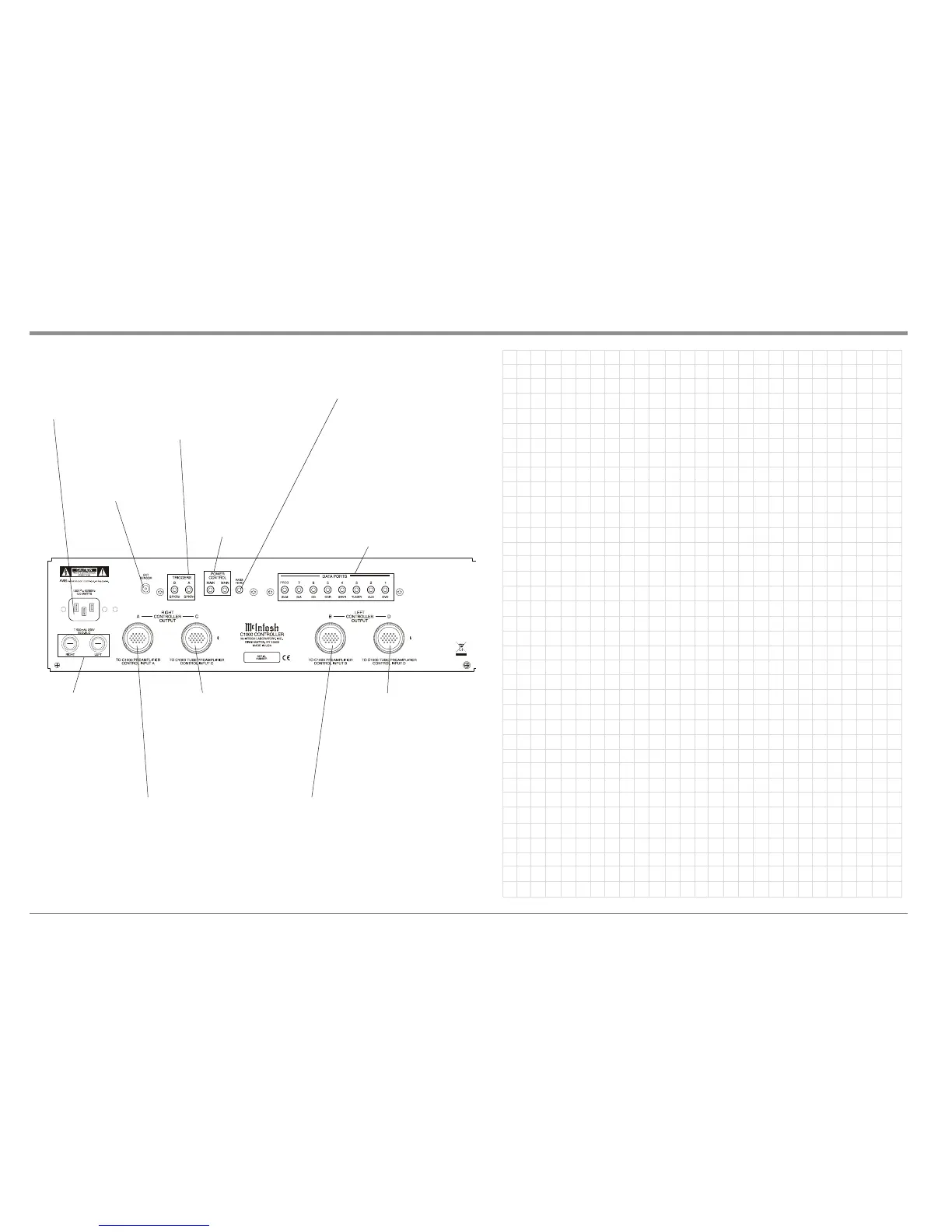
C1000 Controller Rear Panel Connections and Notes
Connect the C1000C
power cord to a live AC
outlet. Refer to informa-
tion on the back panel
of the C1000C to deter-
mine the correct voltage
for your unit
RIGHT and LEFT
Power Supplies
Main Fuse holders,
refer to information
on the back panel of
the C1000C to de-
termine the correct
fuse size and rating
The EXTernal SENSOR
jack permits the con-
nection of a McIntosh
IR sensor for remote
operation
DATA PORTs 1 thru 7 send signals to compat-
ible source components and allow remote con-
trol operation using the C1000C Remote Con-
trol. The PROG/SUM Data Port provides a
summing of signals present at data ports 1-7 by
default. When the PROGramable function is
activated in the Setup Controller Mode, it al-
lows for special control of a McIntosh
MCD1000 CD Player
PASSTHRU Power
Control Input receives
a turn-on signal from
a McIntosh Home
Theater Controller
POWER CONTROL
MAIN Outputs send
a turn-on signal to a
McIntosh Power
Amplifier and Source
Components when
the C1000C is
switched On
RIGHT CONTROLLER OUTPUT A Connector
accepts the custom McIntosh 21 Conductor
Cable. This cable connects to the C1000 RIGHT
PREAMPLIFIER CONTROL INPUT A. It sup-
plies the control signals and power supply volt-
ages for the Right Channel Circuitry in the
Preamplifier
TRIGGERS A (SPKR1) and B (SPKR2) Out-
puts send Turn-On signals to other components
connected to the C1000C. The default setting
is for use with the Spkr1 and Spkr2 Remote
Control Push-buttons. Instead, Trigger Jacks
may be re-assigned to Switch On when a de-
sired Input Source is selected. The Trigger
Voltage is also selectable, 5 Volts for McIntosh
Components or 12 Volts for non-McIntosh
Products.
LEFT CONTROLLER OUTPUT B Connector
accepts the custom McIntosh 21 Conductor
Cable. This cable connects to the C1000 LEFT
PREAMPLIFIER CONTROL INPUT B. It sup-
plies the control signals and power supply volt-
ages for the Left Channel Circuitry in the
Preamplifier
RIGHT CONTROLLER OUTPUT C
Connector
1
accepts the custom McIn-
tosh 21 Conductor Cable.This cable
connects to the C1000 RIGHT TUBE
PREAMPLIFIER CONTROL INPUT
C. It supplies the control signals and
power supply voltages for the Right
Channel Circuitry in the Tube Pream-
plifier
LEFT CONTROLLER OUTPUT D
Connector
1
accepts the custom McIn-
tosh 21 Conductor Cable. This cable
connects to the C1000 LEFT TUBE
PREAMPLIFIER CONTROL INPUT
D. It supplies the control signals and
power supply voltages for the Left
Channel Circuitry in the Tube Pream-
plifier
1
WARNING: The Right Controller Output Connector C Terminals and Left Controller Output Connector D Terminals are haz-
ardous live and present a risk of electric shock. Use only pre-assembled interconnect cables provided by McIn-
tosh for connection of these terminals.