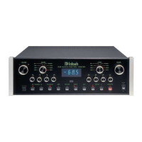
manufactured for Mclntosh Laboratory. It has 32 steps
with a 70dB range, plus volume off. Left and right
channel tracking are within a fraction of 1dB. This ex-
treme accuracy is obtained through special elec-
tronically controlled resistance element trimming.
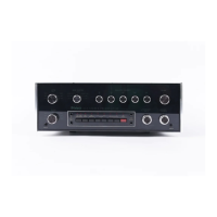
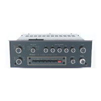
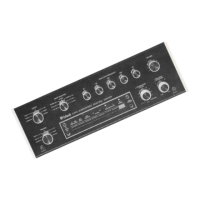
BALANCE AND LOUDNESS:
The BALANCE and LOUDNESS controls are con-
centric. The BALANCE control (large outer knob) ad-
justs the volume of the channels relative to each
other.
L...turning the control to the left accents the left
channel by reducing the right channel output.
R...turning the control to the right accents the
right channel by reducing the left channel output.
LOUDNESS:
The LOUDNESS control (small center knob) pro-
vides a frequency response contour which compen-
sates for the hearing characteristic of the human ear
at lower listening levels. This contour is accurately
modeled after the family of "equal loudness" curves
identified by Fletcher and Munson. At the fully
counterclockwise detented FLAT position, the
loudness contour is electrically flat. As the control
is turned clockwise, both bass and treble frequen-
cies increase in the correct proportion. The contour
is not affected by different settings of the VOLUME
control. After setting the VOLUME control for the
desired listening level, adjust the loudness control
for the preferred compensation.
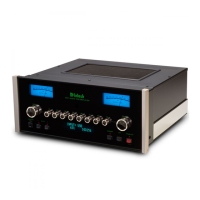
TAPE PUSHBUTTONS:
IMPORTANT: When the C 30 is operated with
either MONITOR pushbutton at the IN position, the
program heard will be that from the tape recorders
only. Signal from any other source will not be heard
from the loudspeakers. To hear any other source,
make sure the MONITOR pushbuttons are OUT.
The MONITOR switches are mechanically in-
terlocked to prevent simultaneous monitoring from
two tape recorders. If one button is at the in posi-
tion, it must be pushed again to release it to the out
position before the other button can be pushed.
The C 30 is designed so that it may be used with
two tape recorders. The four pushbuttons to the left,
control the signal output of these recorders. They
permit recordings to be monitored as they are being
recorded, or copying of tapes from one recorder to
another while listening to a separate program or the
playback of either recorder.
MONITOR TAPE 1 pushbutton out: The program
source as selected by the INPUT SELECTOR is fed
to the power amplifiers and heard through the loud-
speakers; pushbutton in: Signal from a tape recorder
plugged into INPUT TAPE 1 is fed to the power
amplifiers and heard through the loudspeakers.
MONITOR TAPE 2 pushbutton: Functions similar-
ly to monitor Tape 1. It also controls the program
from a tape recorder plugged into the front panel
TAPE IN and OUT jacks. When a tape recorder is
plugged into the front jacks the TAPE 2 IN jacks on
the rear panel are automatically disconnected. The
TAPE 2 outputs are connected at both front and rear
jacks.
TAPE COPY T1
T2 pushbutton in: connects the
output from tape recorder 1 to the input of tape
recorder 2 without affecting the program being
heard from the speakers. In this position a copy of
the the program on tape recorder 1 can be made on
tape recorder 2. To monitor the original, use
MONITOR TAPE 1 pushbutton and to monitor the
copy use MONITOR TAPE 2 pushbutton. When both
MONITOR pushbuttons are out, you hear the pro-
gram from the Input Selector.
TAPE COPY T2 T1 pushbutton in: connects the
output from tape recorder 2 to the input of tape
recorder 1 without affecting the program being
heard from the speakers. In this position a copy of
the tape program on recorder 2 can be made on
recorder 1. To monitor the original use MONITOR
TAPE 2 pushbutton and to monitor the copy use
MONITOR TAPE 1 pushbutton.
SPEAKER OUTPUT 1 AND 2:
The SPEAKER/OUTPUT 1 and 2 pushbuttons can
be used to control either the OUTPUT jacks 1 and 2,
or the main and remote speakers when the optional
SPEAKER CONTROL RELAY (SCR) is connected.
The SPEAKER/OUTPUT pushbuttons should not be
used to control connections to the 1 and 2 jacks and
an SCR for speaker switching at the same time. The
operation of the output jacks and the speaker con-
trol will interfere with each other.
POWER ON:
The POWER ON pushbutton shares AC power
control, through a current detecting switch circuit,
with the AC power switch on a turntable. On the rear
panel the TURNTABLE AUTO/MANUAL switch
selects the mode of operation. When the switch is in
the AUTO position and a turntable is plugged into
the green AC power outlet, the AC power to the
preamp and to the black AC power outlets can be
controlled by the turntable on/off switch. When the
turntable power switch is turned on, the preamplifier
and the SWITCHED black AC power outlets are turn-
ed on. The system will remain on until the turntable
is turned off. The POWER ON pushbutton switch
parallels the automatic turntable power control
feature. The POWER ON pushbutton is used to turn
power on and off when the turntable is not used. The
POWER ON pushbutton must be out or off for the
turntable to control the AC power.
In the MANUAL position only the POWER ON
pushbutton will turn power on or off to the
preamplifier and the black AC power outlets.
13
 Loading...