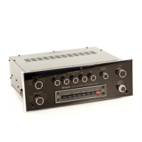
Technical Description
FULL ELECTRONIC SWITCHING:
All input switching including tape, tape-to-tape
and mode is done electronically using J-FET field ef-
fect analog switches. All the front panel switches
control small amounts of DC voltage which turn the
FET analog switches on and off. The critical audio
signals are switched silently with instantaneous
muting between switch positions. No transient swit-
ching noises or pops are present with this superior
design.
PHONO AMPLIFIER:
The phono amplifier uses a high technology in-
tegrated circuit operational amplifier. Its differential
input stage has been optimized for low noise and
low distortion performance. Open loop gain of this
integrated circuit is 100,000. With high open loop
gain a large amount of negative feedback can be us-
ed around the phono amplifier to further reduce
noise and distortion. The feedback network also pro-
vides
precision
RIAA
frequency compensation.
The
network uses 1% metal film resistors and 5% poly
film capacitors. To achieve low noise performance it
is essential that the feedback network be very low
impedance. As a consequence, the preamplifier
must be capable of operating as a power amplifier to
drive this impedance. The actual power output
capability of this preamplifier stage is more than 100
milliwatts, a great margin beyond that which is re-
quired.
Input sensitivity of the phono amplifier is 2
millivolts. The gain of the amplifier is 40dB at
1000Hz. The phono amplifier has a very wide
dynamic range. At 1000Hz the phono input circuit
will accept 100 millivolts without overload, a voltage
far greater than the output of any current magnetic
phono cartridge. Phono input overload therefore is
virtually impossible. A signal level of 10 millivolts at
the phono input at 1000Hz will produce 1 volt at the
tape output. The tape output has a source im-
pedance of 200 ohms, designed to operate into a
load impedance of 10,000 ohms or greater.
HIGH LEVEL AMPLIFIER:
At the input to the high level or loudness amplifier
the signal passes through the mode switch matrix,
then through the volume control, and into the
amplifier. In the past loudness controls have typical-
ly used simple passive circuits connected to a tap
on the volume control. As a consequence, compen-
sation accuracy was dependent on many variables
such as volume control position and differences in
input level. The C 30 uses active circuitry. The same
type of integrated circuit operational amplifier that
is used in the phono amplifier is used here. It has
two feedback loops. One feedback loop has flat
response. The other feedback loop conforms to the
Fletcher-Munson equal loudness compensation. A
potentiometer is placed between these two feed-
back loops making it possible to select any com-
bination of the two from a flat response to full
loudness compensation. The overall gain of the
stage is 15dB and is not affected at mid frequencies
by the position of the loudness control.
EQUALIZER AMPLIFIER;
The equalizer amplifier uses high technology in-
tegrated circuit operational amplifiers. Its output
stage has been optimized for the best transient per-
formance and minimum distortion. Five other opera-
tional amplifiers are each arranged in a circuit con-
figuration that is the equivalent of series tuned cir-
cuits, one at each of the five center frequencies.
Each series tuned circuit is inserted via the control
potentiometer in either the input circuit or feedback
circuit of the operational amplifier thereby providing
a boost and cut capability of 12dB for each band of
frequencies. The overall gain of the stage is 7dB.
FILTER AMPLIFIER;
The C 30 band-pass filter amplifier affects the fre-
quency response at the two extremes of the audio
range. Each channel of the filter amplifier uses the
same type operational amplifier as in the phono
stage and high level amplifier. The resistive and
capacitive elements form a 12dB per octave active
RC filter. High frequencies roll off above 7000Hz,
and low frequencies below 50Hz. The non linear
distortion of the active filter elements in the C 30 is
very low, even at the cutoff frequencies.
HEADPHONE AMPLIFIER:
The C 30 headphone amplifier is capable of driv-
ing two pairs of dynamic headphones and the line
output with less than .007% harmonic distortion.
Maximum output is 9 volts at the line and head-
phone jacks, (1.3 volts with 8 ohm headphones). In-
ternal impedance of the headphone amplifier is 47
ohms at each headphone output and 100 ohms at
the line output. This feature allows the line outputs
to be used with much longer than normal shielded
connecting cables without adversley affecting the
frequency response.
TURN ON DELAY:
The C 30 has a completely transient free turn on
and off. The C 30 is electronically muted for approx-
imately 2 seconds after the AC power is turned on.
This circuit also has a very short turn off time cons-
tant, which mutes the output at turn off before the
preamplifier's main power supply has a chance to
19

 Loading...