12
Spade Lug or Wire Connections:
6. Connect the Loudspeaker hookup cables to the
MA352 Negative Output Terminal and Positive
Output Terminal to the Loudspeaker Terminal
Connections being careful to observe the cor-
rect polarities. Insert the spade lug connector or
prepared section of the cable end into the terminal
side access hole, and tighten the terminal cap until
the cable is firmly clamped into the terminals so
the lugs or wire cannot slip out. Refer to figures L
and M.
Note: The illustration located on the separate folded
sheet “Mc2B” is for connection to an 8Ω
(ohms) Loudspeaker.
Refer to “General Information” Note 6 on page 6
for additional information.
WARNING: Loudspeaker terminals are hazard-
ous live and present a risk of electric
shock. For additional instruction on
making Loudspeaker Connections con-
tact your McIntosh Dealer or McIn-
tosh Technical Support.
7. Connect the MA352 power cord to an active AC
outlet.
Caution: Do not connect the AC Power Cord to the
MA352 Rear Panel until after the Loudspeaker
Connections are made. Failure to observe this
could result in Electric Shock.
The McIntosh MA352 Power Amplifier Circuitry
is designed for Loudspeakers with an impedance of 8
Ohms or 4 Ohms. Connect a single Loudspeaker only
to the Right and Left Output Terminals.
When connecting Loudspeakers to the MA352 it
is very important to use cables of adequate size, so
there is little to no power loss in the cables. The size is
specified in Gauge Numbers or AWG (American Wire
Gauge). The smaller the Gauge number, the larger the
wire size:
Loudspeaker Cable Distance vs Wire Gauge Guide
Loudspeaker
Impedance
25 feet
(7.62 meters)
or less
50 feet
(15.24 meters)
or less
100 feet
(30.48 meters)
or less
4 Ohms
14AWG 12AWG 10AWG
8 Ohms
16AWG 14AWG 12AWG
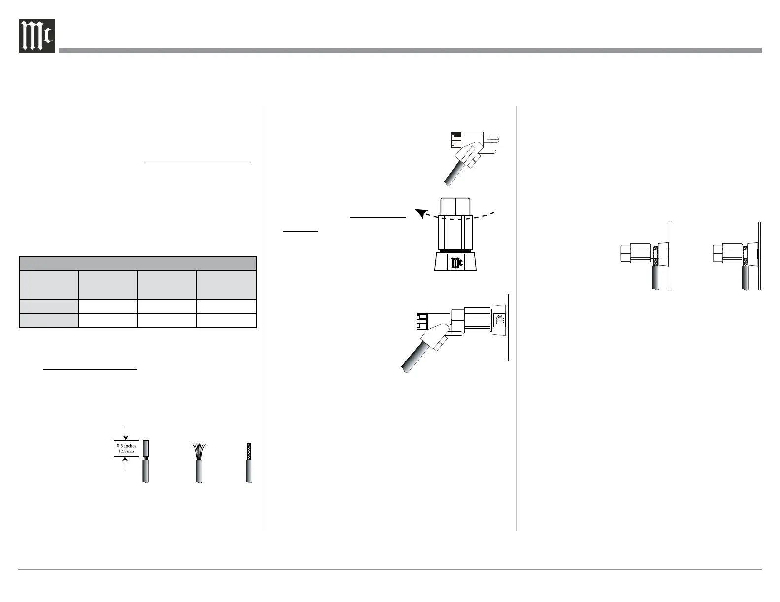
1. Prepare the Loudspeaker Hookup Cable for attach-
ment to the MA352 Power Amplifier:
Bare wire cable ends:
Carefully remove sufficient insulation from the
cable ends, refer to figures F, G & H. If the cable
is stranded, carefully twist the strands together
as tightly as possible.
Notes: 1. If desired, the twisted ends can be tinned
with solder to keep the strands together.
2. The prepared bare wire cable ends may be
inserted into spade lug connectors.
3. Banana plugs are for use in the United
States and Canada only.
Banana Plugs are for use in the United States and
Canada only:
2. Attach the previously prepared bare wire cable ends
into the banana plugs and secure the connections.
Refer to figure I.
3. Rotate the Output Terminal Post
clockwise until it is nger tight.
Refer to gure J. Then using the Mc-
Intosh Wrench, rotate the top of the
Output Terminal one quarter
of a turn (90°). Do not over
tighten.
4. Referring to figure K, con-
nect the Loudspeaker hookup
cables with banana plugs
into the hole at the top of the
terminal to the MA352
Negative Output Terminal
and Positive Output Ter-
minal to the Loudspeaker
Terminal Connections be-
ing careful to observe the
correct polarities.
Note: The illustration
located on the separate folded sheet “Mc2B” is
for connection to an 8Ω (ohms) Loudspeaker.
If the Loudspeaker’s impedance is in-between
the available connections, use the nearest lower
impedance connection. Refer to “General Informa-
tion” Note 6 on page 6 for additional information.
WARNING: Loudspeaker terminals are hazard-
ous live and present a risk of electric
shock. For additional instruction on
making Loudspeaker Connections con-
tact your McIntosh Dealer or McIn-
tosh Technical Support.
5. Connect the MA352 power cord to an active AC
outlet.
Figure F
Figure G
Figure H
Figure I
Figure J
Figure K
Figure L
Figure M
Connecting Loudspeakers
 Loading...