6
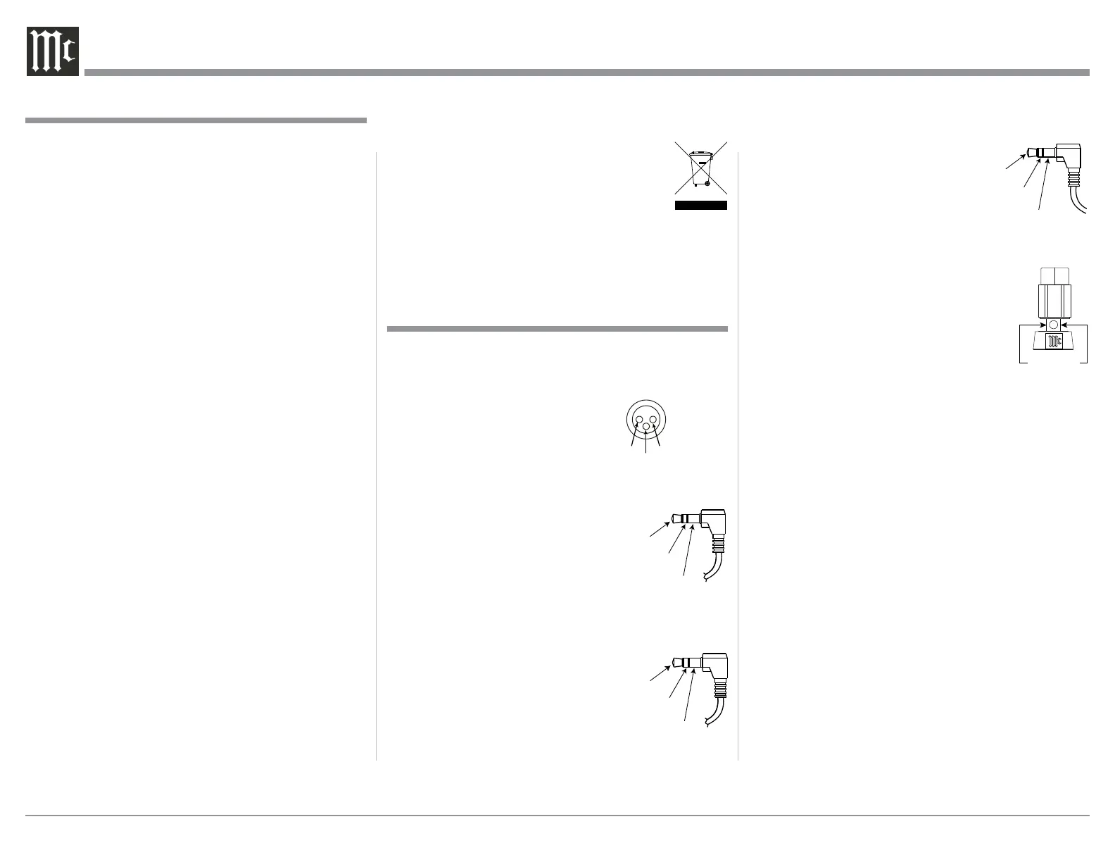
RS232 Data Port Cable
The RS232 Data Cable is a
3.5mm stereo mini phone plug
for use with a compatible control
system.
Output Terminal Connector
When cables with spade lugs are used
for Loudspeaker Connection, the spade
lugs need an opening of at least 3/10 inch
(7.6m m).
XLR Connectors
Below is the Pin configuration for the XLR Balanced
Input Connectors on the MA352. Refer to the diagram
for connection:
PIN 1: Shield/Ground
PIN 2: + Output
PIN 3: - Output
Power Control Connector
The Power Control Output Jack sends Power On/
Off Signals (+12 volt/0 volt) when
another McIntosh Component is
connected. A 3.5mm stereo mini
phone plug is used for connection to
the Power Control Output.
Data Port Connector
The Data Out Ports send Remote Control Signals to
Source Components. A 3.5mm stereo
mini phone plug is used for connec-
tion.
1. For additional connection information, refer to the
owner’s manual(s) for any component(s) connected
to the MA352.
2. Apply AC Power to the MA352 and other McIntosh
Component(s) only after all the system components
are connected together. Failure to do so may cause
a malfunction of system operations as the Micro-
processor’s Circuitry inside the components is
active when AC Power is applied.
3. The MA352 includes an Auto Off Power Save
Feature and the default setting is enabled. For
additional information including how to disable it,
refer to page 21.
4. When Power Amplifier Protection Circuitry of the
MA352 has activated, the Vacuum Tubes LEDs are
illuminated continuously with the color orange and
the sound will be muted.
5. When the Power Transformer has overheated due
to improper ventilation and/or high ambient operat-
ing temperature, AC Power is removed from the
MA352. Normal operation will resume when the
operating temperature is in a safe range again.
6. The MA352 Remote Control is capable of operating
other components. For additional information go to
www.mcintoshlabs.com.
7. The IR Input, with a 3.5mm mini phone jack, is
configured for non-McIntosh IR sensors such as
a Xantech Model HL85BK Kit. Use a Connection
Block such as a Xantech Model ZC21 when two
or more IR sensors need to be connected to the
MA352. The signal from a connected External IR
Sensor will have priority over the signal from the
Front Panel IR Sensor.
8. When discarding the unit, comply with local rules
or regulations. Batteries should never be
thrown away or incinerated but disposed
of in accordance with the local regula-
tions concerning battery disposal.
9. For additional information on the MA352 and
other McIntosh Products please visit the McIntosh
Website at www.mcintoshlabs.com.
Connector and Cable Information
Data
Signal
N/C
Data
Ground
General Information
PIN 1
PIN 2
PIN 3
General Information, Connector and Cable Information
3/10 of an inch
(7.6millimeters)
Power
Control
Ground
N/C
Data In
(DB9-pin2)
Ground
(DB9-pin5)
Data Out
(DB9-pin3)