EasyManuals Logo

McIntosh MA352 User Manual

McIntosh MA352
28 pages
To Next Page IconTo Next Page
To Previous Page IconTo Previous Page
Page #9 background imageLoading...
Page #9 background image
9
Installation
Installation
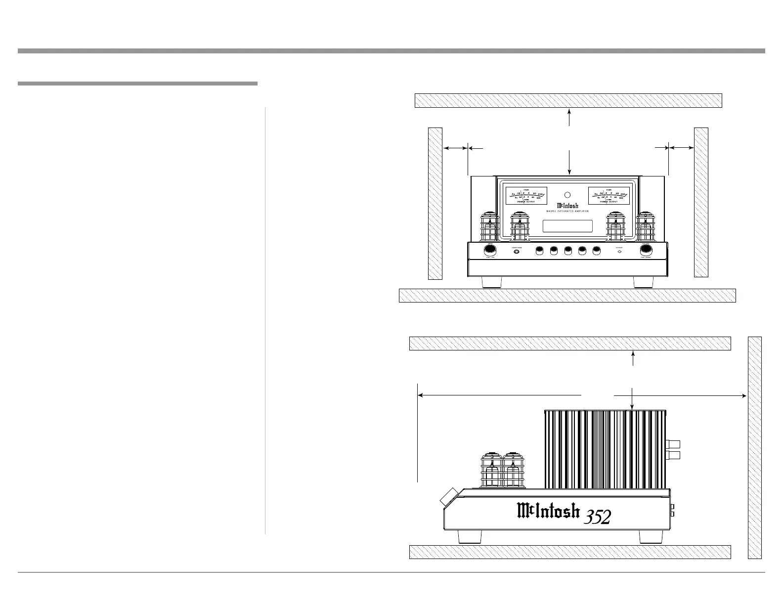
The MA352 Integrated Amplifier is designed to be
placed upright on a table or shelf, standing on its feet.
The required ventilation requirements are shown.
Always provide adequate ventilation for your MA352.
Cool operation ensures the longest possible operating
life for any electronic instrument. Do not install the
MA352 directly above a heat generating device, such
as a Power Amplifier. Allow at least 6 inches (15.3cm)
above the top, 5/8 inch (1.6cm) below the bottom and
2 inches (5.1cm) on each side of the Amplifier, so that
airflow is not obstructed. Allow 22 inches (55.9cm) of
depth for airflow and cable connections.
MA352 Side View
22"
55.9cm
MA352 Front View
6"
15.3cm
6"
15.3cm
2"
5.1cm
2"
5.1cm
30
125
500
2K 10K
BAL 1
15%

Questions and Answers:

Question and Answer IconNeed help?

Do you have a question about the McIntosh MA352 and is the answer not in the manual?

McIntosh MA352 Specifications

General IconGeneral
Total Harmonic Distortion0.03%
Number of Channels2
Speaker Impedance4, 8 Ohms
Rated Power Band20Hz to 20kHz
Headphone OutputYes
Home Theater PassThruYes
TypeIntegrated Amplifier
Input Impedance (Line)20K ohms
Input Impedance (MM)47K ohms, 50pF
Frequency Response+0, -0.5dB from 20Hz to 20kHz
Signal to Noise Ratio100dB
Preamplifier Inputs1 Balanced
Variable Output1
Phono InputMoving Magnet
Vacuum Tube or Solid StateHybrid (Vacuum Tube and Solid State)
Vacuum Tube Complement2 x 12AX7A, 1 x 12AT7
Input Sensitivity0.5V (Balanced)
Input Impedance20K ohms Balanced, 20K ohms Unbalanced

Related product manuals