5
McIntosh Plug-In Jumper Connector
The MA/MAC6700 utilizes a phono style Plug-In
Jumper to connect the Preamplifier
Output to the Power Amplifier Input, one
Jumper for each channel.
Note: The Jumper Connector is available
from the McIntosh Parts Department:
McIntosh Jumper Connector Part No. 117781
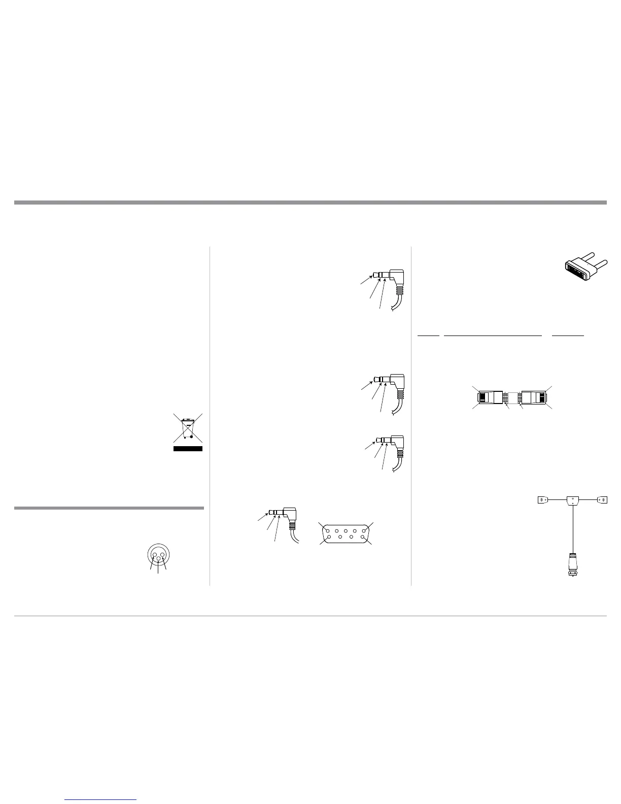
RAA2 Cable Connector
Pin No. Wire Color Pin No. Wire Color
1. White/Orange 5. White/Blue
2. Orange 6. Green
3. White/Green 7. White/Brown
4. Blue 8. Brown
*Cable outer shield
Note: The RAA2 Connecting Cable is available from the
McIntosh Parts Department:
RAA2 Antenna Cable Part No. 171844
Twenty foot, shielded 8 conductor, with a shielded
RJ45 connector on each end.
FM Dipole Antenna
The MAC6700 Tuner Module or the addition of the
optional Tuner Module for the
MA6700 require the connec-
tion of an external Antenna for
FM reception. A “FM Dipole
Antenna” is available from the
McIntosh Parts Department:
FM Dipole Antenna Part
No. 173033
Power Control and Trigger Connectors
The Power Control Trigger Output Jacks send and
Passthru Input Jack receives Power
On/Off Signals (+12 volt/0 volt)
when connected to other McIntosh
Components. An additional connec-
tion is for controlling the illumina-
tion of the Power Output Meters
on McIntosh Power Amplifiers. A
3.5mm stereo mini phone plug is used for connection
to the Power Control, Trigger and Passthru Outputs.
Data Port Connectors
The Data Out Ports send Remote Control Signals to
Source Components. A 3.5mm stereo
mini phone plug is used for connec-
tion.
IR IN Port Connectors
The IR IN Port also uses a 3.5mm stereo mini phone
plug and allows the connection of
other brand IR Receivers to the MA/
MAC6700.
RS232-C Data Port Cable
The RS232 Data Cable is a 3.5mm stereo mini phone
plug to a sub minature DB 9 connector:
XLR Connectors
Below is the Pin configuration for the XLR Balanced
Input Connectors on the MA/MAC6700. Refer to the
diagram for connection:
PIN 1: Shield/Ground
PIN 2: + Output
PIN 3: - Output
with the impedance of the Loudspeaker at low
frequencies where the greatest amount of power
is required. Contact the Loudspeaker Manufac-
turer for additional information about the actual
impedance of the Loudspeaker before connecting
it to the McIntosh MA/MAC6700.
8. The MA/MAC6700 Remote Control is capable of
operating other components. For additional infor-
mation go to www.mcintoshlabs.com.
9. The IR Input, with a 1/8 inch mini phone jack, is
configured for non-McIntosh IR sensors such as
a Xantech Model HL85BK Kit. Use a Connection
Block such as a Xantech Model ZC21 when two or
more IR sensors need to be connected to the MA/
MAC6700. The signal from a connected External
IR Sensor will have priority over the signal from
the Front Panel IR Sensor.
10. When discarding the unit, comply with local rules
or regulations. Batteries should never be
thrown away or incinerated but disposed
of in accordance with the local regula-
tions concerning battery disposal.
11. For additional information on the MA/MAC6700
and other McIntosh Products please visit the Mc-
Intosh Web Site at www.mcintoshlabs.com.
Connector and Cable Information
Data
Signal
N/C
Data
Ground
Power
Control
Meter
Illumination
Control
Ground
Main, Trig 1&2
and Pass-Thru
PIN 1
PIN 2
PIN 3
IR Data
Control
Ground
N/C
Pin 1
Pin 1
Pin 8
Pin 8
*Cable outer shield
General Information, Connector and Cable Information
PIN 1
PIN 6
PIN 5
PIN 9
Data In
(DB9-pin2)
Ground
(DB9-pin5)
Data Out
(DB9-pin3)
DB9
(male connector)
 Loading...