16
Technical Description
In the late 1940s Frank McIntosh and Gordon Gow
invented and patented a new output circuit arrange-
ment for audio power amplifiers, the McIntosh Unity
Coupled Output Circuit. Refer to figure 19. This cir-
cuit has two
very impor-
tant features
that differen-
tiate it from
other de-
signs. First,
the output
tubes deliver
their power
from both
their plates
and their
cathodes, not
from their
plates alone as in conventional circuits. Second, the
Unity Coupled Output Transformer, having two bifi-
lar primary windings (one for the plate and the other
for the cathodes), has one half the turns ratio (equat-
ing to one fourth the impedance ratio) of conven-
tional output transformers. The resulting benefits are
much lower distortion produced in the output stage
and improved transformer design giving very close
coupling primary to secondary for flat frequency re-
sponse and wide power bandwidth.
MC2000 Application
The MC2000 uses the Unity Coupled Output Circuit
with KT-88 or 6550 output tubes in a push-pull paral-
lel configuration. These tube types are selected be-
cause of their excellent power and voltage ratings
plus the favorable experience McIntosh has had with
them in the MC275 and other amplifier models. The
output tubes deliver signal to the output transformer
through two primary windings, one for the plates and
the other for the cathodes. These windings are wound
bifilar, which means that both windings are wound
together, two wires, at the same time. The secondary
consists of five separate wind-
ings interspersed within the pri-
mary windings. These five
windings are connected in par-
allel. Very tight coupling is ob-
tained, which achieves wide
bandwidth and flat frequency
response. The transformer core
is four and one half square
inches of grain oriented silicon
steel. This allows full power
output down to 17 hertz.
Refer to figure 20, MC2000
Block Diagram of the Amplifier
Section.
The output tubes operate
with fixed bias, which is adjust-
able and metered as explained
later. Because the output tubes
are loaded in their cathodes,
they require a large grid drive
signal of approximately 170
volts for full output. This signal
is provided by the 12AT7 driver
stage. The plates of the driver
are resistance-capacitance
coupled to the output tubes.
Plate loading for the driver is
boot strapped to the plate wind-
ing of the output transformer.
Boot strapping increases the effective plate load to
the driver providing greater amplification than other-
wise possible. A Darlington emitter follower stage is
used at the grids of the output tubes to provide a rela-
tively low impedance to eliminate possible bias run-
away due to output tube grid current.
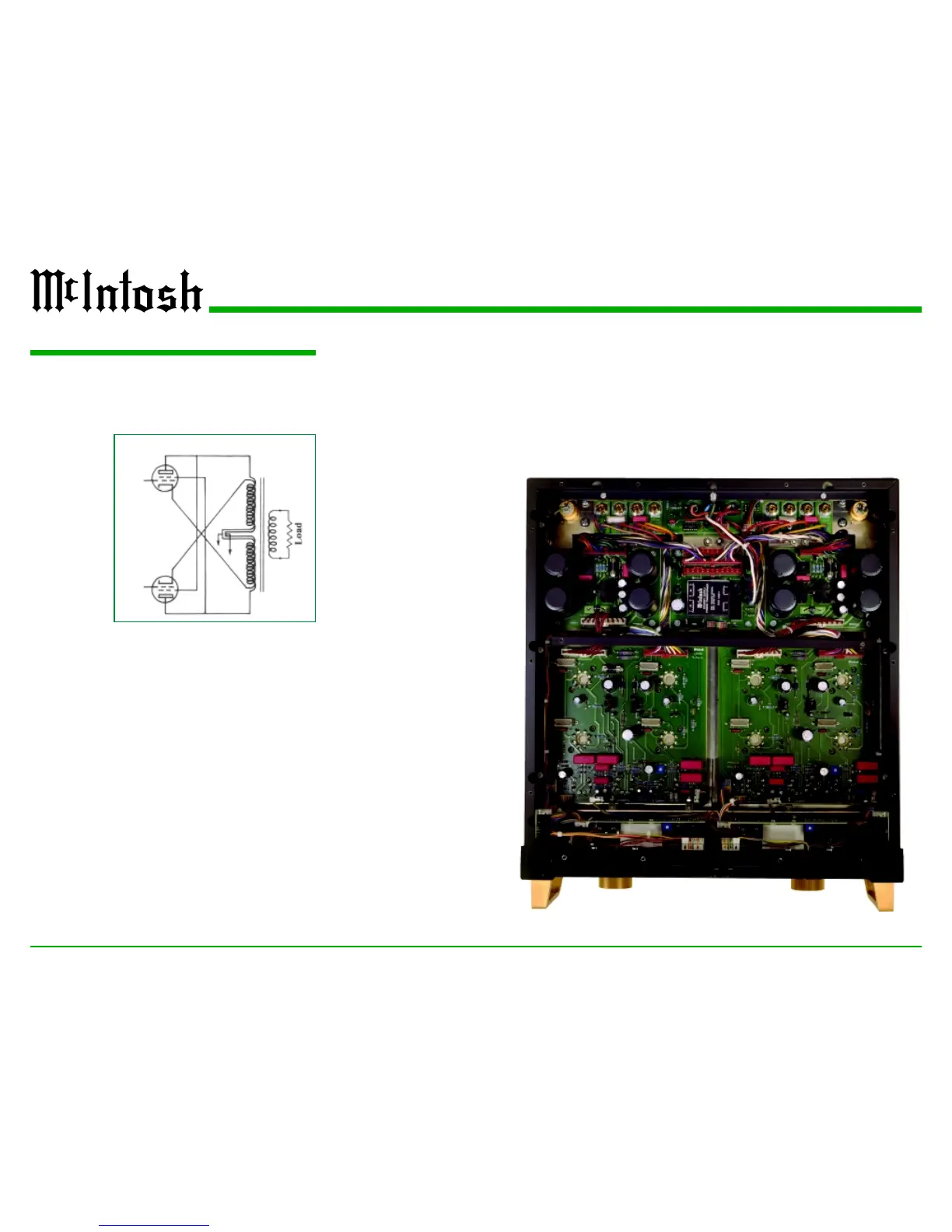
Figure 19
McIntosh Unity Coupled Output Circuit
Inside of the MC2000
 Loading...