8
Installation of Tubes and Cover
Your MC2000 has gone through an extensive series
of performance tests during the manufacturing pro-
cess. The actual tubes that were used to test and con-
firm the performance of this amplifier are included in
the McIntosh MC2000 Tube Set Box, refer to figure
3. Inside the tube set box is a plastic overlay that
identifies each tube and its specific socket location in
the amplifier. The MC2000 Chassis has nomenclature
screened on it to specify both the circuit location and
tube type for each channel, refer to figure 4. It is ex-
tremely important to insert the tubes in the correct
location. Below is an example for installing one of
the power output and small signal tubes into the
MC2000 Tube Sockets for Left Channel:
Caution: To prevent electrical shock make sure that the
MC2000 AC POWER CORD IS NOT
CONNECTED to the unit when inserting or
removing tubes, as there are hazardous
voltages present at the pins of the tube sockets.
Note: White gloves have been provided to prevent
fingerprinting of the Vacuum Tubes during
their installation into the MC2000.
Power Output Tubes:
1. Locate tube V4L (KT88 or 6550) in the Tube
Set Box (Left side of the Box).
2. Locate the matching tube socket on the
MC2000 Chassis (Left side of the Amplifier).
3. Orient the tube so that the key on the base of the
tube is aligned with the corresponding key on
the tube socket.
4. Carefully insert the tube into the socket until the
base of the tube is fully seated in the tube
socket.
5. Repeat the above the steps for the remaining 7
Power Output Tubes, refer to figure 5.
Small Signal Tubes:
1. Locate tube V1L (12AX7A) in the Tube Set
Box (left side of the box).
Note: There are two different types of small tubes
(12AX7A and 12AT7) used in each channel. The
MC2000 will not function if they are inserted into
the wrong socket.
2. Locate the matching tube socket on the
MC2000 Chassis (left side of the amplifier).
3. Orient the tube so that the area where no pins
are located on the base of the tube is aligned
with the corresponding area on the tube socket.
4. Carefully insert the tube into the socket until the
base of the tube is fully seated in the tube
socket.
5. Repeat the above steps for the remaining 5
Small Signal Tubes, refer to figure 5.
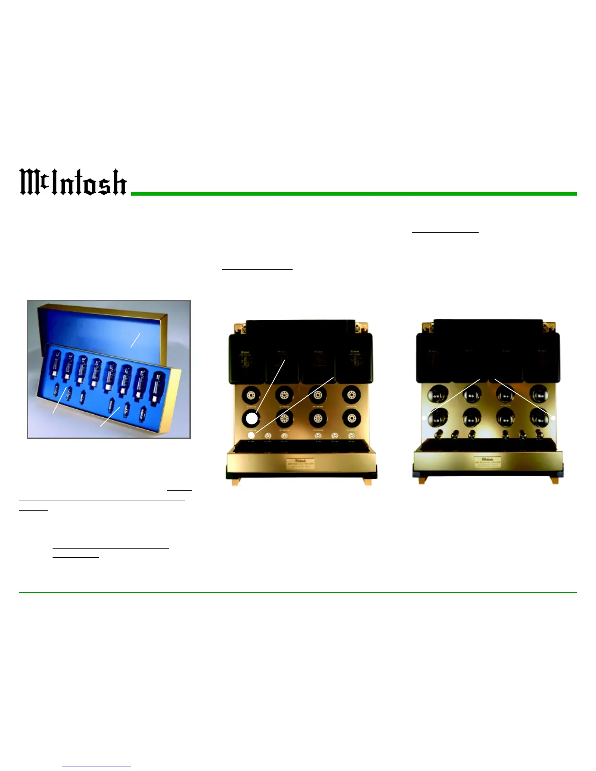
Figure 3
Plastic Overlay
Left Channel Tubes
Right Channel Tubes
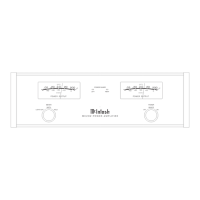
Figure 4
V4L (KT88/6550)
V1L (12AX7A)
Figure 5
Shipping Screws Location
 Loading...