17
Technical Description
higher distortion of many non-feedback designs.
All transistors are selected to have nearly constant cur-
rent gain over the entire current range they must cover.
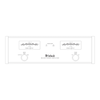
Output transistors in par-
ticular, have matched
uniform current gain,
high current-bandwidth
product and large active
region safe operating
area. To accommodate
the high current demands
of a 4 ohm loudspeaker,
the MC207 Output Cir-
cuitry utilizes a multi-
plicity of power output
transistors. Refer to fig-
ure 14. An automatic
tracking bias system
completely eliminates
any trace of crossover
distortion. Precision
metal film resistors and
low dielectric absorption
film capacitors are used
in all critical circuit loca-
tions.
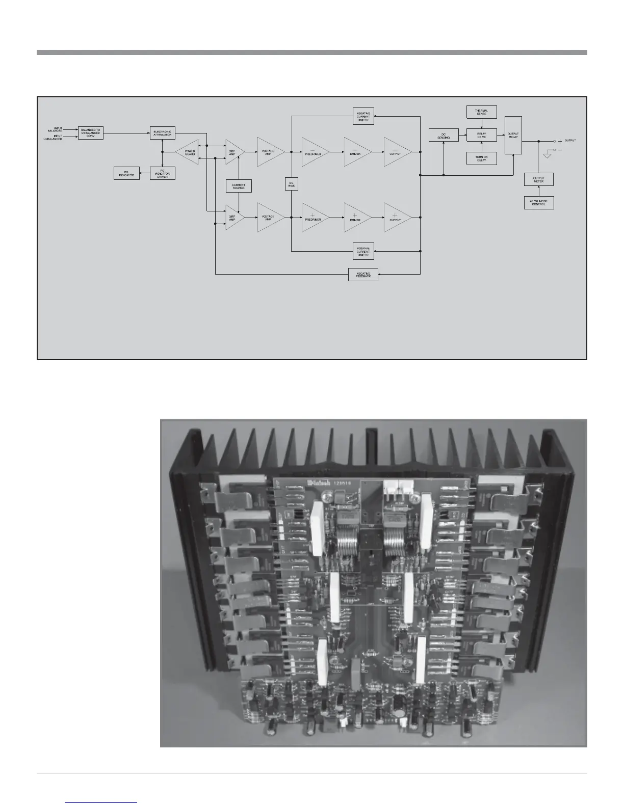
Figure 13
Block Diagram of the Amplifiers
and
Meter Circuitry
(One of Seven Channels Illustrated)
Figure 14
The MC207 is the first McIntosh Power Amplifier to
use the newly developed Dynamic Power Manager
TM
(DPM) Circuitry. Refer to figure 15 on the next page.