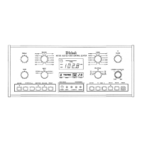
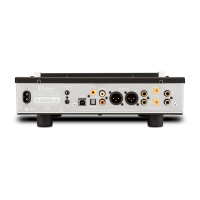
THE
REAR PANEL
AND HOW
TO MAKE
CONNECTIONS
Use high quality cables to interconnect the audio and video accessory equipment us-
ed with your MX 130 Audio/Video Tuner Control Center. This will ensure the best possi-
ble performance from your Mclntosh Audio/Video Tuner Home Theater and Stereo
system. Your Mclntosh dealer can advise you on the types and lengths of cables best
suited for your particular installation.
ALL SIGNALS FED TO THE SIX UNBALANCED OUTPUTS ALSO APPEAR AT THE
MX130 REAR PANEL 6 CHANNEL OUTPUT CONNECTOR AND ARE FED THROUGH
AN OPTIONAL 25 CONDUCTOR SUBMINIATURE "D" MALE-TO-FEMALE COMPUTER
TYPE CABLE TO A MATCHING CONNECTOR ON A MclNTOSH MC7106 SIX CHANNEL
POWER AMPLIFIER. THE CHANNEL IS AS FOLLOWS:
CHANNEL 1: Center Front
CHANNEL 2: Left Surround
CHANNEL 3: Left Front
CHANNEL 4: Right Front
CHANNEL 5: Subwoofer
CHANNEL 6: Right Surround
1. SUR (SURround)
Connect a pair of cables from the SURround AUDIO OUTPUT jacks to the inputs of the
power amplifier channels which will feed left and right surround sound loudspeakers.
2. CENTER
Connect a cable from the CENTER AUDIO OUTPUT jack to the amplifier channel that will
feed a center front loudspeaker.
3. SUBWOOF(SUBWOOFer)
Connect a cable from the SUBWOOFer AUDIO OUTPUT jack to the amplifier channel
feeding a subwoofer loudspeaker. This output includes only audio frequencies of 80Hz and
lower.
4. FRONT
Connect a pair of cables from the FRONT AUDIO OUTPUT jacks to the left and right front
amplifiers. Use these outputs if you are operating the MX 130 as a conventional two channel
control center.
These same signals that feed the FRONT AUDIO OUTPUT jacks also feed the BALANCED
OUTPUTS, (See No. 19.)
5. VCR1, VCR2
Connect cables from the MX 130 VCR1 and VCR2 AUDIO OUTPUT jacks to the high level
audio inputs of two VCR units. These connections allow you to record the audio portion of
ANY input selected by the RECORD switch.
6. TAPE 1, TAPE 2
Connect cables from the MX 130 TAPE1 and TAPE2 AUDIO OUTPUT jacks to the high level
inputs of two audio tape recorders. These connections allow you to record the audio portion
of ANY input selected by the RECORD switch.
7. RECORD PROCESSOR, FROM AND TO
An external signal processor can be added to the MX 130 which will affect audio recording
signals only at the VCR1, VCR2, TAPE 1 and TAPE 2 audio outputs. The PROCESSOR FROM
jacks have built-in switching contacts that allow normal signals to pass through when no cables
18