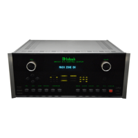
THE
REAR PANEL
AND
HOW TO MAKE
CONNECTIONS
3. An outdoor antenna designed specifically for the FM broadcast band is the best for op-
timum reception in all areas. In fringe areas, a directional FM antenna with a rotor is recom-
mended. A rotor allows you to position the antenna for the best possible reception of a specific
FM station. Consult your Mclntosh dealer for assistance if you decide to install an outdoor
FM antenna system.
4. A signal from your local cable company can also be connected- Consult your Mclntosh
dealer and the cable company for installation assistance.
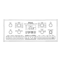
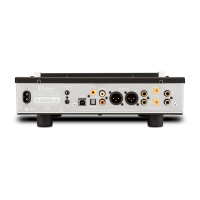
15 and 16. AUX (Auxiliary) and PH (PHono)
Both the PHono and Auxiliary inputs are selected by the same position on the front panel
LISTEN and RECORD selector switches. Either the PHono or Auxiliary inputs can be used,
but not both at the same time. When a pair of cables is connected to the Auxiliary input
jacks, the PHono section is automatically bypassed.
Auxiliary: Connect a pair of cables from the outputs of an accessory component to the
AUX INPUTS.
To use the PHono inputs, FIRST remove any cables connected to the AUX inputs.
PHono: Connect a pair of cables from a record player with a moving magnet phono car-
tridge to the PH INPUTS.
AUX: Connect a pair of cables from the high level outputs of an accessory component
to the AUX inputs.
17. GND (Ground)
If the phono player being used has a separate ground lead, connect it to the GND terminal.
18. AM LOOPSTICK ANTENNA
When the MX 130 is packed for shipping, the AM loopstick antenna is folded flat and taped
against the rear panel. Remove the securing tape and fold it out, away from the panel for
proper AM reception. The AM loopstick antenna is directional so it is designed to be easily
moved to a wide range of positions. This allows you to move the loopstick to the position
for the best possible reception of your favorite AM stations.
19. L and R BALANCED OUTPUTS
Connect cables with XLR type Balanced Connectors from the MX 130 L (Left) and R (Right)
BALANCED OUTPUT jacks to the balanced input jacks of the power amplifier. Signals at the
BALANCED jacks are present whenever the MX130 Area "A" is on and operating, and are
the same signals as at the Unbalanced Left Front and Right Front Outputs.
Using balanced connectors and cables can reduce noise and interference by as much
as 40dB. This extra noise reduction can be a significant improvement, especially if the cables
are quite long.
If two separate mono power amplifiers are used with the MX130 to reproduce the
Left and Right Front signals, balanced cables can eliminate the possibility of hum
pickup.
If cable lengths between the MX130 and the power amplifiers are one meter or less, you
may find high quality unbalanced cables to be satisfactory.
Balanced Jack Pin Configuration:
Pin 1. System Ground
Pin 2. + Output
Pin 3. - Output
20