PERFORMANCE SPECIFICATIONS con’t
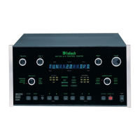
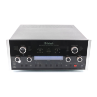
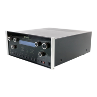
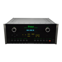
MX136
1. The heavy lines on the schematic denote the primary
signal path.
2. Unless otherwise noted, all voltages indicated on the
schematics are measured under the following conditions:
a. AC input at 120 volts, 50/60Hz.
b. All voltages are +/-10% with respect to ground. A
high impedance (10 megaohm) voltmeter must be used.
3. On PC board drawings, Square pad indicates:
a. Polarized Capacitors - Positive
b. Diodes - Cathode
c. Others - Pin 1
4. WARNING
Parts marked with the symbol have critical
characteristics. Use only replacement parts recom-
mended by the manufacturer.
NOTES
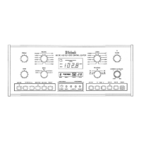
REAR PANEL
3
Capture Ratio
1.2dB
Alternate Channel Selectivity
75dB
Spurious Response
100dB
Image Response
75dB
RF Intermodulation
65dB
Stereo Separation
45dB at 100Hz
45dB at 1,000Hz
35dB at 10,000Hz
SCA Rejection
65dB
AM Tuner Specifications
Sensitivity
20uV External Antenna Input
Signal To Noise Ratio
48dB at 30% modulation
58dB at 100% modulation
Harmonic Distortion
0.5% maximum at 50% modulation
Frequency Response
50Hz to 6kHz NRSC
Adjacent Channel Selectivity
45dB minimum IHF
Image Rejection
65dB minimum from 540 to 1600kHz
IF Rejection
80dB minimum