48
IMM AGS-2
Remote Evaporator
This section contains data that is unique to AGS-CM/B remote evaporator models
including:
• Refrigerant piping on page 49.
• Dimensions on page 51.
• Vibration isolators on page 58.
• Physical data on page 60.
Data common to both packaged and remote evaporator models are:
• Electrical data on page 32.
• Evaporator pressure drop, on page 25.
Piping Layout
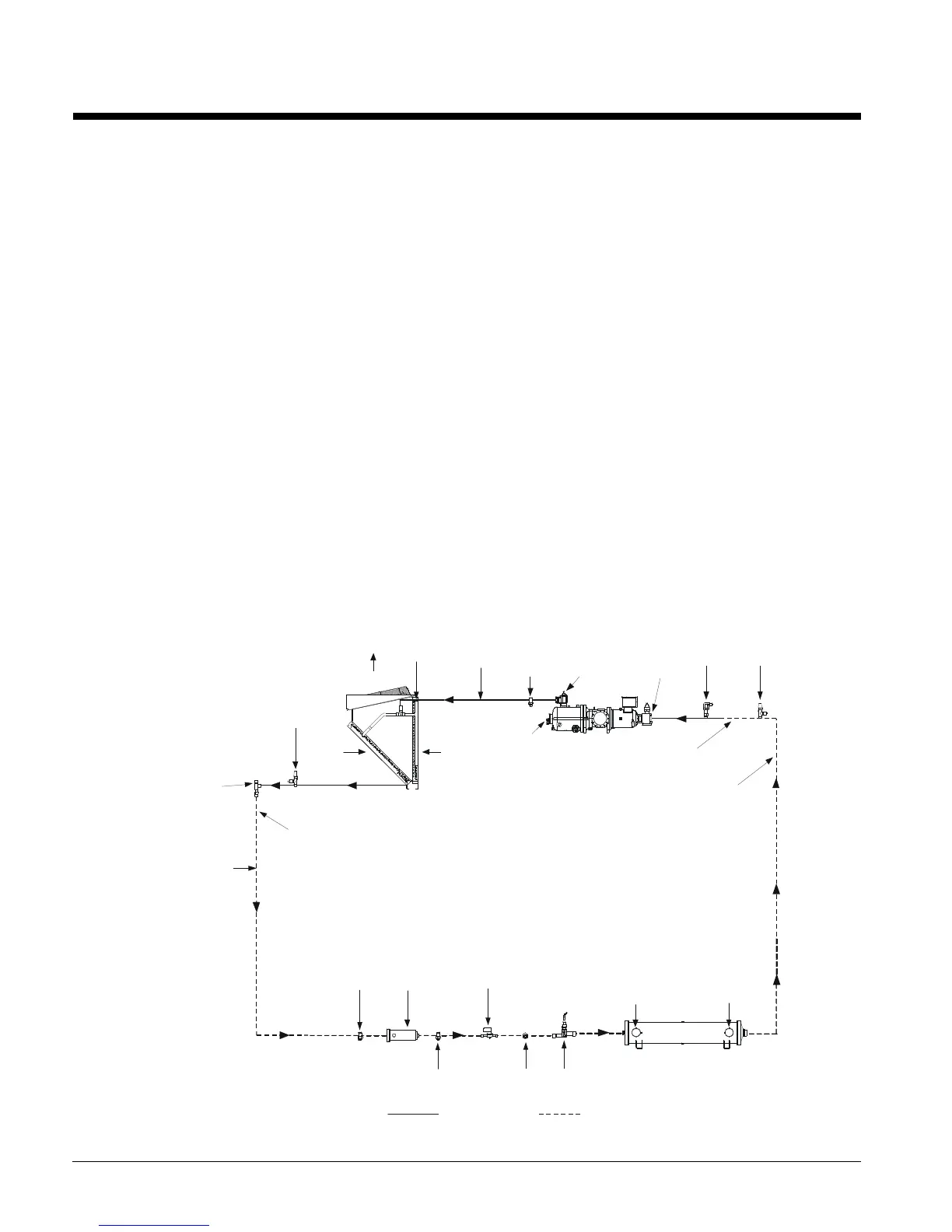
Figure 26 shows the piping layout for one of the two refrigerant circuits for AGS units with
a remote evaporator. Note that the refrigerant specialties are field installed adjacent to the
evaporator. The outdoor unit, the evaporator, and a kit of refrigerant components are
shipped as separate pieces. The outdoor unit is shipped with an operating charge of
refrigerant. Refrigerant for the evaporator and field refrigerant piping is furnished by the
contractor and must be added in the field.
The location and size of the refrigerant (and water) connections are shown on the
dimension drawings beginning on page 51. Looking at the control panel, circuit #1 is on
the left, #2 on the right.
NOTE: All field piping, wiring, and procedures must be performed in accordance with
ASHRAE, EPA, and industry standards.
Figure 26, Piping Schematic (Remote Evaporator)
CHARGING
VALVE
LIQUID
TUBING
LIQUID
SHUT-OFF
VALVE
SCHRADER
VALVE
FILTER
DRIER
SCHRADER
VALVE
SOLENOID
VALVE
SIGHT
GLASS
EXPANSION
VALVE
WATER OUT
SUCTION LINE
SHUT-OFF
VALVE
TUBING
SCHRADER
VALVE
DISCHARGE
TUBING
AIR
FLOW
AIR
FLOW
AIR
FLOW
CONDENSOR
ASSEMBLY
FRAME 3200
COMPRESSOR
RELIEF
VALVE
VALVE
RELIEF
VALVE
FIELD CONNECTION
LIQUID LINE
SCHRADER
VALVE
(HEADER)
FIELD PIPING
SHUT-OFF
VALVE
 Loading...


