IMM AGS-2
71
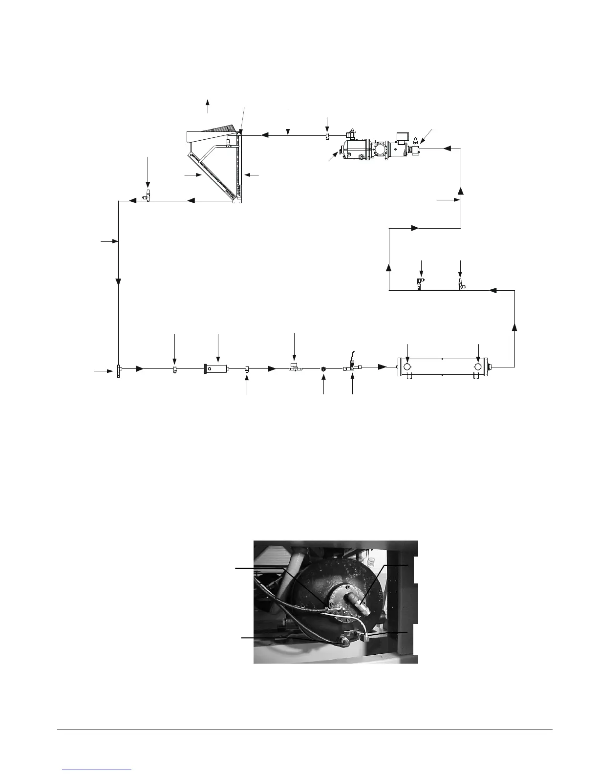
Figure 39, Piping Schematic, One of Two Circuits
CHARGING
VALVE
LIQUID
TUBING
LIQUID
SHUT-OFF
VALVE
SCHRADER
VALVE
FILTER
DRIER
VALVE
SIGHT
VALVE
(OPTIONAL)
TUBING
SCHRADER
VALVE
DISCHARGE
TUBING
AIR
FLOW
AIR
FLOW
AIR
FLOW
CONDENSOR
ASSEMBLY
FRAME 3200
COMPRESSOR
RELIEF
VALVE
CHARGING
VALVE
RELIEF
VALVE
VALVE
(HEADER)
The above diagram illustrates one of the two circuits of an AGS chiller. The evaporator has
two single-pass circuits with water passing over baffles on the shell side.
The vertical and slanted coils on one side of the unit comprise a condensing circuit. Models
AGS 180C through 210C have an external economizer circuit consisting of a brazed-plate
heat exchanger and expansion valve (not shown on the above diagram).
Figure 40, Compressor-mounted Components
Compressor Relief Valve
Optical Oil Level Sensor
Mechanical High
Pressure Cutout Switch
Oil Heater
 Loading...


