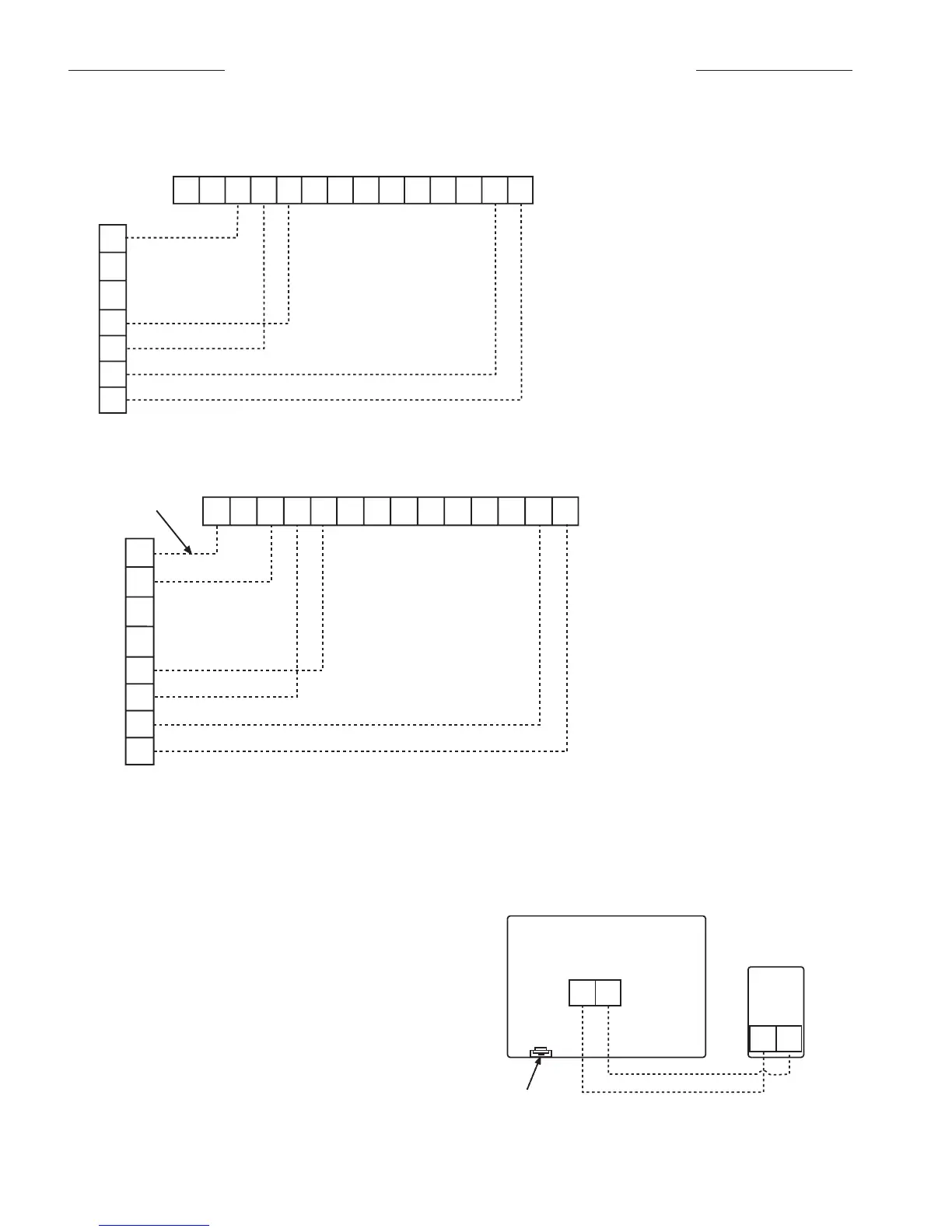
1. Remove cover from remote sensor housing.
2. Select an appropriate location for mounting the remote
sensor.
3. Mount remote sensor unit using hardware provided.
4. Install two strand shielded wire between remote sensor
and thermostat. Shielded wire must be used.
Do not run remote sensor wire in conduit with other wires.
• Wire 1 should run between the S1 terminal on the ther
-
mostat and the S1 terminal on the remote sensor
• Wire 2 should run between the S2 terminal on the ther-
mostat and the S2 terminal on the remote sensor
• Connect the shielding of the wire to the S2 terminal on
the thermostat
5. Disable the main sensor (R12) on the thermostat by
cutting it from the circuit board.
Page 16 / IM 742
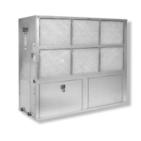
WSHP Mark IV/AC Board Low Voltage Terminal Strip (Circuit 1)
O W
2 G
W1 Y1 F E L U A P V R C
W1 Y1 W2 Y2 G
Thermostat Terminals
-
C
+
R
7-Day Programmable Electronic Thermostat (P/N 107095901)
Thermostat Connection Diagrams
Mark IV/AC Units – Unit Sizes 007-070
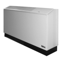
Non-Programmable Electronic Thermostat (P/N 668054201)
WSHP Mark IV/AC Board Low Voltage Terminal Strip (Circuit 1)
O
W1 Y1 F E L U A P V R C
W1 Y1 W2 Y2 G O
Thermostat Terminals
Override (Optional)
-C +R
W2 G
Includes Thermostat and Wall Plate.
Notes:
When remote reset of a lockout condition
is required at the wall thermostat, it will be
necessary to utiilize a conductor between
terminal "O" on the wall thermostat to termi-
nal "O" on the Mark IV control board (non-
programmable stat only).
Refer to the installation, operation & appli-
cation guide (LIA204-4) for thermostat
668054201 installation details
Optional Remote Sensor (P/N 667720401)
S1
S2
S1
S2
Cut R12 from
circuit board
Remote Senso
Includes Thermostat and Wall Plate.
Refer to the installation, operation & application
guide (LIA217) for thermostat 107095901 installa-
tion details
 Loading...