Page 26 / IM 742
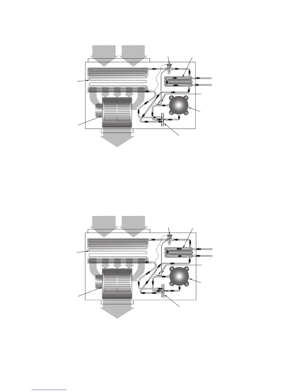
Cooling Mode – (Single Circuit Only Shown)
Return Air
Reversing Valve
Conditioned Air – (Cooling)
Thermal
Expansion Valve
Co-Axial Heat
Exchanger
Blower
Coil – Air to Refrigerant
Heat Exchanger
Water In
Water Out
Sensing Bulb and
Capillary Tube
Compressor
Heating Mode – (Single Circuit Only Shown)
Return Air
Thermal
Expansion Valve
Co-Axial Heat
Exchanger
Reversing Valve
Conditioned Air – (Heating)
Blower
Water In
Water Out
Sensing Bulb
and Capillary Tube
Compressor
Coil – Air to Refrigerant
Heat Exchanger
Cooling Refrigeration Cycle
When the wall thermostat is calling for COOLING, the reversing valve directs the flow of the refrigerant, a hot gas, leaving the
compressor to the water-to-refrigerant heat exchanger. Here the heat is removed by the water and the hot gas condenses to
become a liquid. The liquid then flows through a thermal expansion metering system to the air-to-refrigerant heat exchanger
coil. The liquid then evaporates becoming a gas, at the same time absorbing heat and cooling the air passing over the surfaces
of the coil. The refrigerant then flows as a low pressure gas through the reversing valve and back to the suction side of the
compressor to complete the cycle.
Heating Refrigeration Cycle
When the wall thermostat is calling for HEATING, the reversing valve directs the flow of the refrigerant, a hot gas, leaving the
compressor to the air-to-refrigerant heat exchanger coil. Here the heat is removed by the air passing over the surfaces of the
coil and the hot gas condenses to become a liquid. The liquid then flows through a capillary thermal expansion metering system
to the water-to-refrigerant heat exchanger. The liquid then evaporates becoming a gas, at the same time absorbing heat and
cooling the water. The refrigerant then flows as a low pressure gas through the reversing valve and back to the suction side of
the compressor to complete the cycle.
Typical Refrigeration Cycles
 Loading...