IM 742 / Page 5
Electrical Data
1. Verify the compatibility between the voltage and phase
of the available power and that shown on the unit serial
plate. Line and low voltage wiring must comply with
local codes or the National Electrical Code, whichever
applies.
2. Apply correct line voltage to the unit. A
7
⁄8" (22mm) hole
and/or a 1
1
⁄8" (29 mm) knockout is supplied on the side
of the unit. A disconnect switch near the unit is required
by code. Power to the unit must be sized correctly and
have dual element (Class RK5) fuses or an HACR circuit
General
breaker for branch circuit overcurrent protection. See the
nameplate for correct ratings.
3. Three phase 50 cycle units, 380/50/3, require a neutral
wire for 230/50/1 power to the fan circuit.
4. Connect the thermostat/subbase wiring with the power
“off ” to the unit.
5.
Field supplied relays installed on the input terminals W1, W2, Y1,
Y2 or G may introduce electrical noise. Never install relay coils in
series with the inputs.
230 Volt Operation
Fan Assembly
All 208-230 volt single-phase and three-phase units are
factory wired for 208 volt operation. For 230 phase opera
-
tion, the line voltage tap on the 24 volt transformer must be
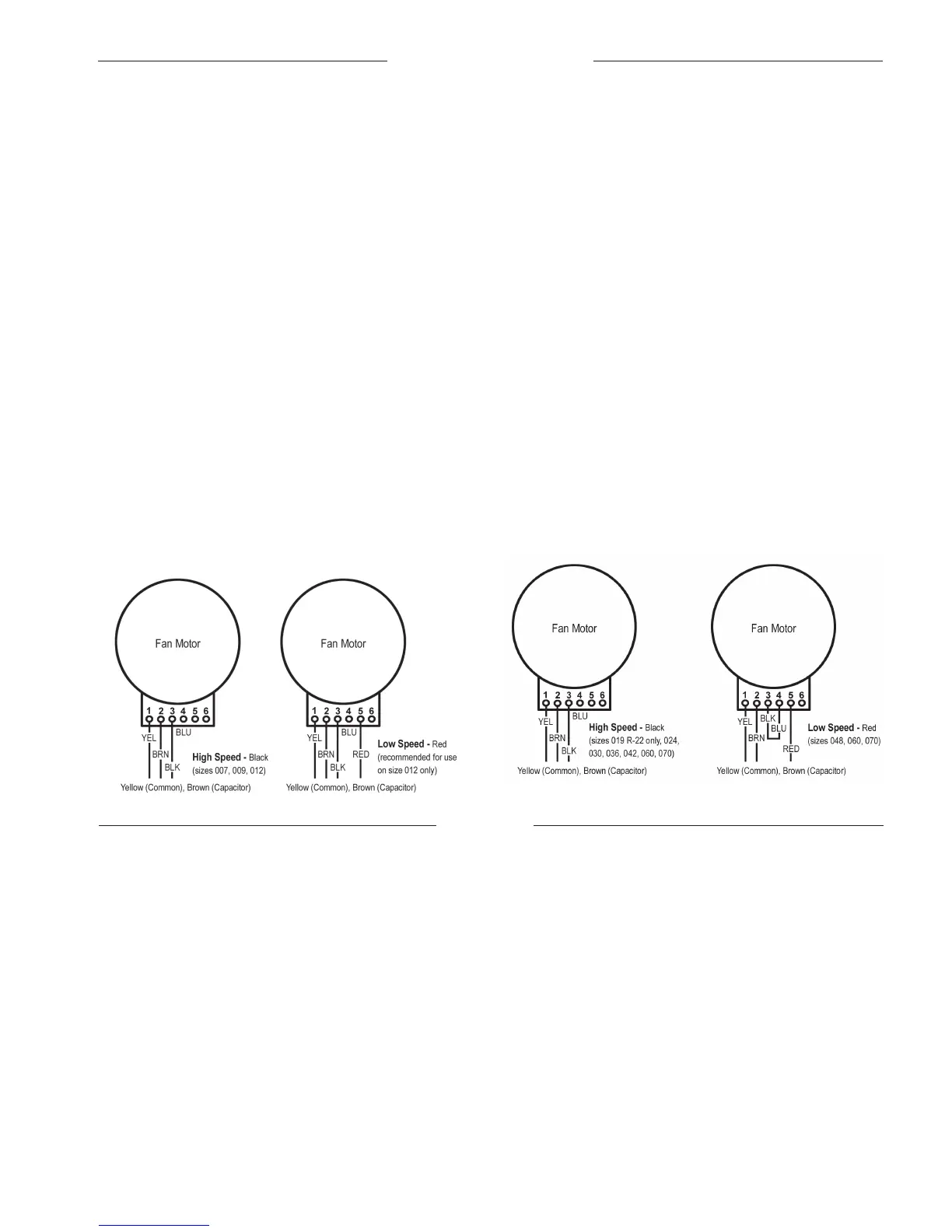
All fan motors are multi-speed, PSC type with integral
mounting brackets and thermal overload protection. The
motor is isolated from the fan housing for minimum vibration
transmission. Fan motors on 019 thru 070 have a terminal
strip on the motor body for simple motor speed change
without going back to the control box. To change fan motor
speed to high on size 015 through 048, interchange the red
wire with the black wire. For low speed, sizes 012, 024,
030, 036, 042, 060 and 070, interchange the black wire with
the red wire. To change the 460 volt motor from high to low
speed, interchange Black and Red wires, then add jumper
between Black and Blue wires. All the fan/motor assemblies
have a removable orifice ring on the housing to accommo-
date motor and fan wheel removal without disconnecting the
ductwork. The fan housing protrudes through the cabinet
allowing adequate material for connection of flexible duct.
Each model unit is shipped from the factory for maximum
performance and minimum sound requirements. Fan sound
levels and performance can be affected by external static
pressure.
changed. Disconnect and cap the red lead wire and inter-
change it with the orange lead wire on the primary of the 24
volt transformer.
Piping
1. All units should be connected to supply and return pip-
ing in a two-pipe reverse return configuration. A reverse
return system is inherently self-balancing and requires
only trim balancing where multiple quantities of units
with different flow and pressure drop characteristics
exist in the same loop. Check for proper water balance
by measuring differential temperature reading across
the water connections. To insure proper water flow, the
differential flow should be 10°F to 14°F (5°C to 8°C) for
units in cooling mode.
A direct return system may also work acceptably, but
proper water flow balancing is more difficult to achieve
and maintain.
2. The piping can be steel, copper or PVC.
3. Supply and return runouts usually join the unit via short
lengths of high pressure flexible hose which are sound
attenuators for both unit operating noise and hydraulic
pumping noise. One end of the hose should have a
swivel fitting to facilitate removal for service. Hard pip
-
ing can also be brought directly to the unit. This option
is not recommended since no vibration or noise attenu-
ation can be accomplished. The hard piping must have
unions to facilitate unit removal. See Figure 5 for typical
piping setup.
4. Some flexible hose threaded fittings are supplied with
sealant compound. If not, apply Teflon tape to assure a
tight seal.
5. Supply and return shutoff valves are required at each
conditioner. The return valve is used for balancing and
should have a “memory stop” so that it can always be
closed off but can only be reopened to the proper posi-
tion for the flow required.
6. No unit should be connected to the supply and return
piping until the water system has been cleaned and
flushed completely. After the cleaning and flushing
has taken place, the initial connection should have
all valves wide open in preparation for water system
flushing.
Figure 4. CCH, CCW, CRH & CRW Sizes 007 thru 070
(Factory wired)
Note: For low speed applications a jumper must be installed between the motor's Black and
Blue terminal.
Figure 4a. CCH, CCW, CRH & CRW Sizes 042 thru 070
(Factory wired, 460 volt motor only)
 Loading...