24 IM710
.
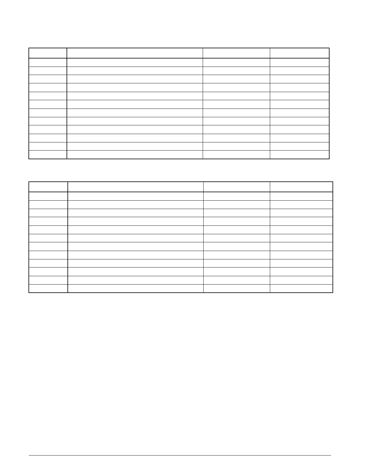
Table 11: Binary Inputs for Circuit #1 through Circuit #4 Auxiliary Cooling Control Board (CCB1)
Binary Input Input Description 24 VAC Present Indication Continuity Present
CCB1-BI1 High Pressure Switch, Circuit #1 (HP1) N/A Normal
CCB1BI2 High Pressure Switch, Circuit #2 (HP2) N/A Normal
CCB1-BI3 High Pressure Switch, Circuit #3 (HP3) N/A Normal
CCB1-BI4 High Pressure Switch, Circuit #4 (HP4) N/A Normal
CCB1-BI5 Low Pressure Switch, (LP1) & Frost Protection Switch (FP1) N/A Both Switches Closed
CCB1-BI6 Low Pressure Switch, (LP2) & Frost Protection Switch (FP2) N/A Both Switches Closed
CCB1-BI7 Low Pressure Switch, (LP3) & Frost Protection Switch (FP3) Both Switches Closed N/A
CCB1-BI8 Low Pressure Switch, (LP4) & Frost Protection Switch (FP4) Both Switches Closed N/A
CCB1-BI9 Compressor #1 Contactor Auxiliary Switch Status M1 Contactor Energized N/A
CCB1-BI10 Compressor #2 Contactor Auxiliary Switch Status M2 Contactor Energized N/A
CCB1-BI11 Compressor #3 Contactor Auxiliary Switch Status M3 Contactor Energized N/A
CCB1-BI12 Compressor #4 Contactor Auxiliary Switch Status M4 Contactor Energized N/A
Table 12: Binary Inputs for Circuit #5 and #6 Auxiliary Cooling Control Board (CCB2)
Binary Input Input Description 24 VAC Present Indication Continuity Present
CCB2-BI1 High Pressure Switch, Circuit #5 (HP5) N/A Normal
CCB2-BI2 High Pressure Switch, Circuit #6 (HP6) N/A Normal
CCB2-BI3 Not Used - -
CCB2-BI4 Not Used - -
CCB2-BI5 Low Pressure Switch, (LP5) & Frost Protection Switch (FP5) N/A Both Switches Closed
CCB2-BI6 Low Pressure Switch, (LP6) & Frost Protection Switch (FP6) N/A Both Switches Closed
CCB2-BI7 Not Used - -
CCB2-BI8 Not Used - -
CCB2-BI9 Compressor #5 Contactor Auxiliary Switch Status M5 Contactor Energized N/A
CCB2-BI10 Compressor #6 Contactor Auxiliary Switch Status M6 Contactor Energized N/A
CCB2-BI11 Spare - -
CCB2-BI12 Spare - -