28 IM710
When a capacity decrease is required, the "Lag" compressor
with the most hours is turned off. When a further capacity
decrease is required, the remaining "Lag" compressor is
turned off. When a further capacity decrease is required, the
"Lead" compressor is staged off.
For detailed information regarding circuit lead/lag operation,
refer to the "Compressor Staging" section of the applicable
operation manual (refer to Table 1 on page 3). Disabled
compressors are not turned on.
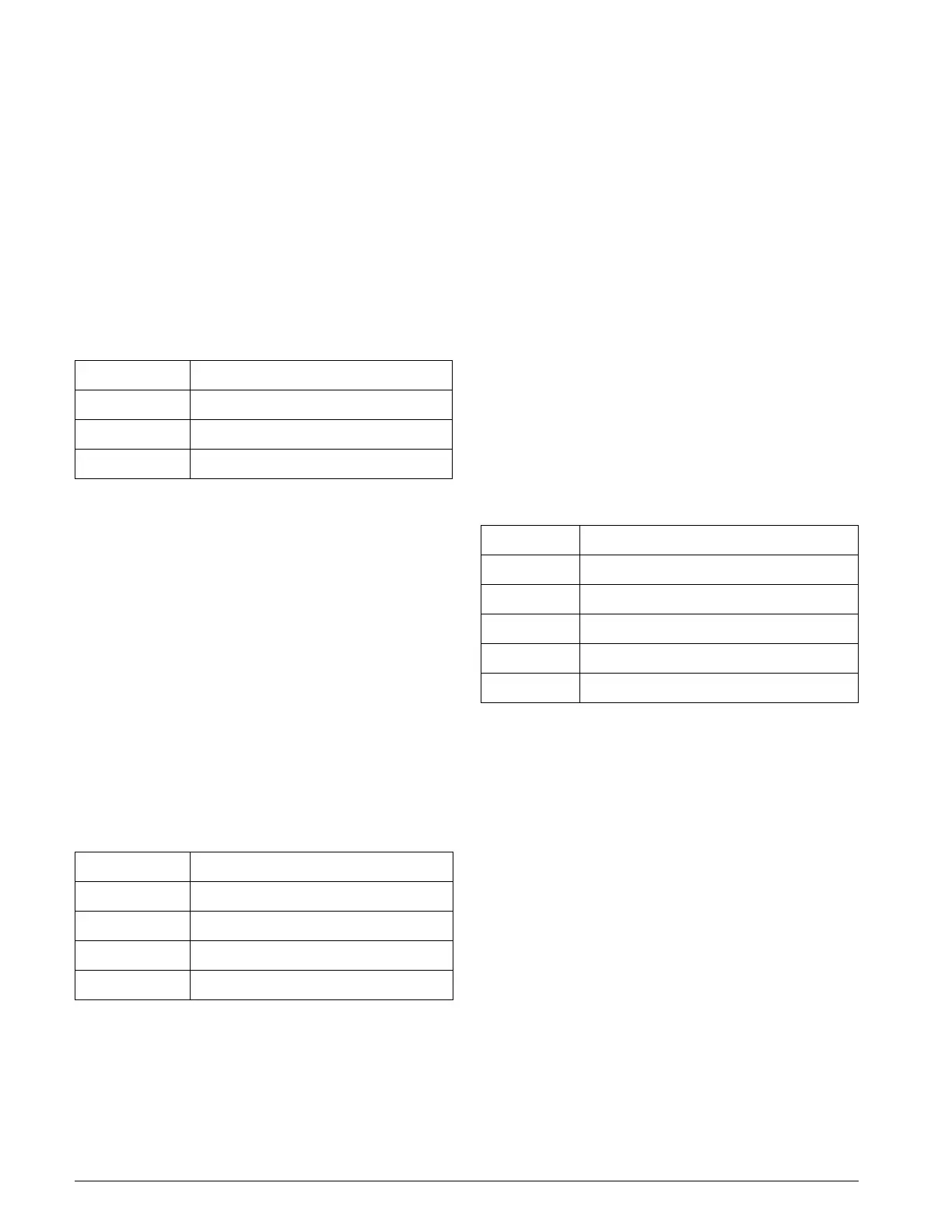
Table 16 summarizes the staging sequencing for the 3-Com-
pressor/3-Stage cooling configuration.
Table 16: 3 Compressors / 3 Stages
4-Compressors/4-Stage
There are four compressors and four independent cooling
circuits. The unit capacity is increased or decreased by turn-
ing compressors on and off. Compressors #1 and #2 provide
the first two stages of cooling. The compressor with the
fewest run hours is staged on first and turned off last. Com-
pressors #3 and #4 provide the last two stages of cooling.
The compressor with the fewest run hours is staged on first
and turned off last. For detailed information regarding cir-
cuit lead/lag operation, refer to the "Compressor Staging"
section of the applicable operation manual (refer to Table 1
on page 3). Disabled compressors are not turned on.
Table 17 summarizes the staging sequencing for the 4-Com-
pressor/4-Stage cooling configuration.
Table 17: 4 Compressors / 4 Stages
3-Small Compressors
& 1-Large compressor/5-Stage
There are three equally sized small compressors and one
large compressor. Each compressor is on an independent
cooling circuit. The unit capacity is increased or decreased
by staging compressors on and off. Compressors #1 or #2
provide the first stage of cooling. The compressor with the
fewest run hours is staged on first and staged off last. Com-
pressors 1 and 2 provide the second stage of cooling. When
further capacity is required, an operating small compressor is
turned off and the large compressor is staged on to provide
the third stage of cooling. When further capacity is required,
Compressors #1 or #2 will provide the fourth stage of cool-
ing. Compressor #3 provides the last stage of cooling.
Note: Stages 3 and 4 are skipped when the large compres-
sor is disabled. The next enabled small compressor
in the sequence is staged on when one or more of
the small compressors is disabled and a stage up is
required.
Table 18 summarizes the staging sequencing for the 3-Small
Compressors & 1-Large compressor/ 5-Stage cooling con-
figuration.
Table 18: 3-Small Compressors & 1-Large compressor/
5-Stage
2-Small Compressors
& 2-Large Compressors/6-Stage
There are two equally sized small compressors and two
equally sized large compressors. Each compressor is on an
independent cooling circuit. The unit capacity is increased
or decreased by staging compressors on and off. The small
compressors #1 or #2 provide the first stage of cooling. The
compressor with the fewest run hours is staged on first and
staged off last. The second stage of cooling turns on the
remaining small compressor (#1 or #2). The third stage of
cooling turns off either #1 or #2 and stages on either #3 or
#4. The third stage has one small and one large compressor
operating. The fourth stage of cooling stages on the remain-
ing small compressor. The fifth stage of cooling turns off one
of the small compressors and stages on the remaining large
compressor. If further cooling is required, the remaining
small compressor is staged on to provide the sixth stage of
cooling. Disabled compressors are ignored. The next
enabled compressor in the sequence is turned on when one or
more compressors are disabled and a stage up is required.
Stages Compressors
11 or 2
2 1,2 or 1,3 or 2,3
3 1,2,3
Stages Compressors
11 or 2
21,2
3 1,2, (3 or 4)
4 1,2,3,4
Stages Compressors
11 or 2
21,2
3 1 or 2,4
4 1,2,4
5 1,2,3,4

 Loading...


