IM 882 / Page 9 of 36
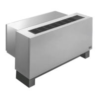
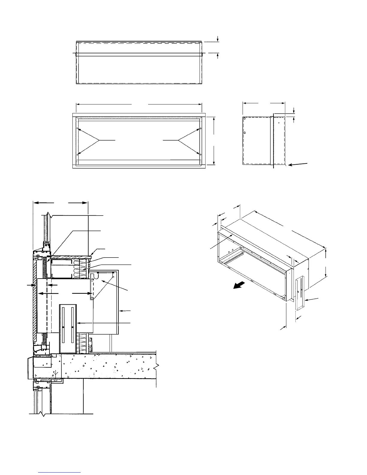
Figure 10. Wall sleeve installation for thin wall
construction
Notes:
** See table on page 6, for dimensions “D” and “B”.
* Dimension
“X” is eld determined or specied. Angle is factory welded at given dimension when option is designated.
Optional
Continuous
Flange
B**
Leveling Leg
to Support
Cabinet
Hydronic Heat
Coil Section
3-1/2" Thick
Batt Insulation
1-5/8" Metal Stud 16" O.C.
Window Stool
Insulation Wet Panel
16"
1
1
/
4
"
42"
Outdoor Side of
Sleeve
X*
6
3
/
8
"
Optional
Leveling Leg
13-3/4"
X*
D**
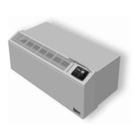
Figure 11. 16" x 42" wall sleeve with optional leveling
legs and continuous ange
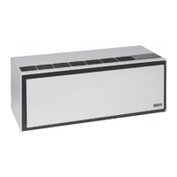
Figure 9. 16" x 42" wall sleeve with continuous ange and drip edge
16"
42"
D**
Louver Mounting Holes
Flange Height
(Standard = 1-1/4")
Flange location (from outdoor side of sleeve)
is factory provided in increments of 1/8"
X*
Drip Edge
Note:
Given dimensions are standard.