McQuay IM 987 37
Mechanical Installation
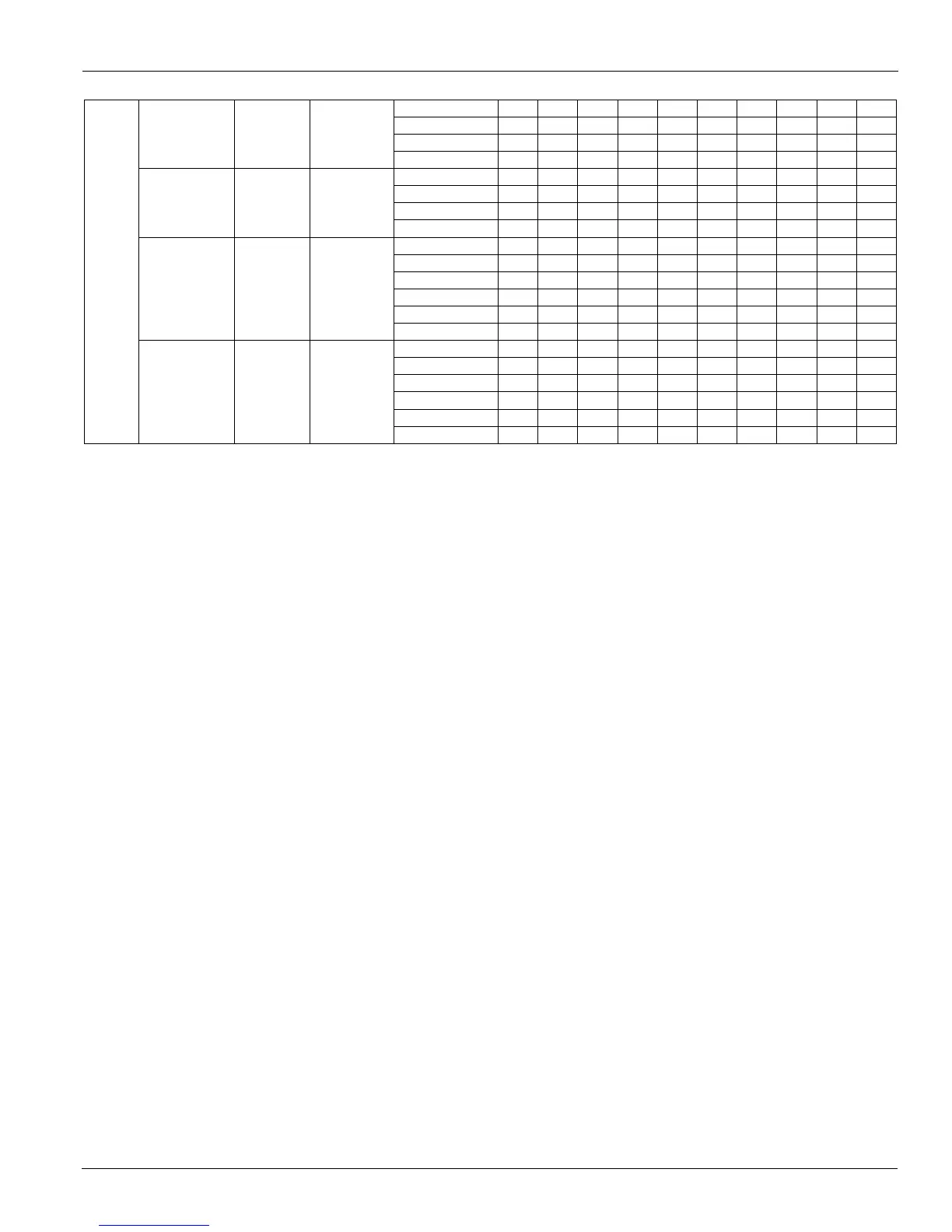
Table 10 Available Circuiting Legend
Column 1:
These units are available with a factory installed package consisting of a three-way water valve and connecting piping.
A = This combination is not available with a factory-installed piping and valve package.
B = 300, 2.50, or 200 inch three-way valves can be specified
C = 300, 2.50, 2.00, or 150 inch three-way valves can be specified
D = 250, 200, or 150 inch three-way valves can be specified
E = 250, 200, 150, or 1.25 inch three-way valves can be specified
F = 200, 1.50, or 125 inch three-way vales can be specified
G = 1.25, 1.50, 2.00 or 2.50 inch three-way valves can be specified
Field supply and return female NPT connection sizes are the same as the valve size.
Column 2:
The following letters designate units that are not furnished with the factory installed piping/valve package. Required are field sweat
connections, at one or two coils, to male copper tubing for the supply and return water piping.
K = A single 2.00 inch NPT supply and return if fin height is 21–30 inches and 2.50 inches of fin height is 30–36 inches.
L = A single 1.50 inch NPT supply and return
M = A single 2.00 inch NPT supply and return if fin height is 21–30 inches
N = A single 2.50 inch NPT supply and return
P = Two 3.12 inch O.D. supply and two 3.12 O.D. return connections
Q = Two 2.62 inch O.D supply and two 2.62 O.D. return connections
R = Two 2.12 inch O.D. supply and two 2.12 O.D. return connections
S = One 3.12 inch O.D supply and one 3.12 O.D. return connections
T = One 2.62 inch O.D supply and one 2.62 O.D. return connections
U = One 2.12 inch O.D supply and one 2.12 O.D. return connections
800
or
802
Blow-thru or
draw-thru cooling
only coil section
48 + 78
(1220 +
1981 mm)
26.0
(2.42 m²)
3 G T G T ——————
4 GTGTGT————
5 G T G T ——————
6 GTGTGT————
Blow-thru or
draw-thru unit
coil section
48 + 78
(1220 +
1981 mm)
26.0
(2.42 m²)
3 G T G T ——————
4 GTGTGT————
5 G T G T ——————
6 GTGTGT————
Face and bypass
section with
small coil
30 + 79
(763 +
2006 mm)
16.5
(2.57 m²)
3 — L —M——— N— N
4 — L —M—M—N—N
5 — L —M——— N— N
6 — L —M—M—N—N
8 — L —M—M—N—N
10 — L —M——— N — N
Blow-thru or
draw-thru
contractor coil
section
36 + 79
(915 +
2006 mm)
19.8
(4.18 m²)
3—L—M—K—N—N
4 — L —M——— N— N
5—L—M—K—N—N
6—L—M—K—N—N
8—L—M—K—N—N
10 — L — M — K — N — N
Table 10: Piping Connection Sizes/Valve Size Options for Chilled Water Piping