60 McQuay IM 987
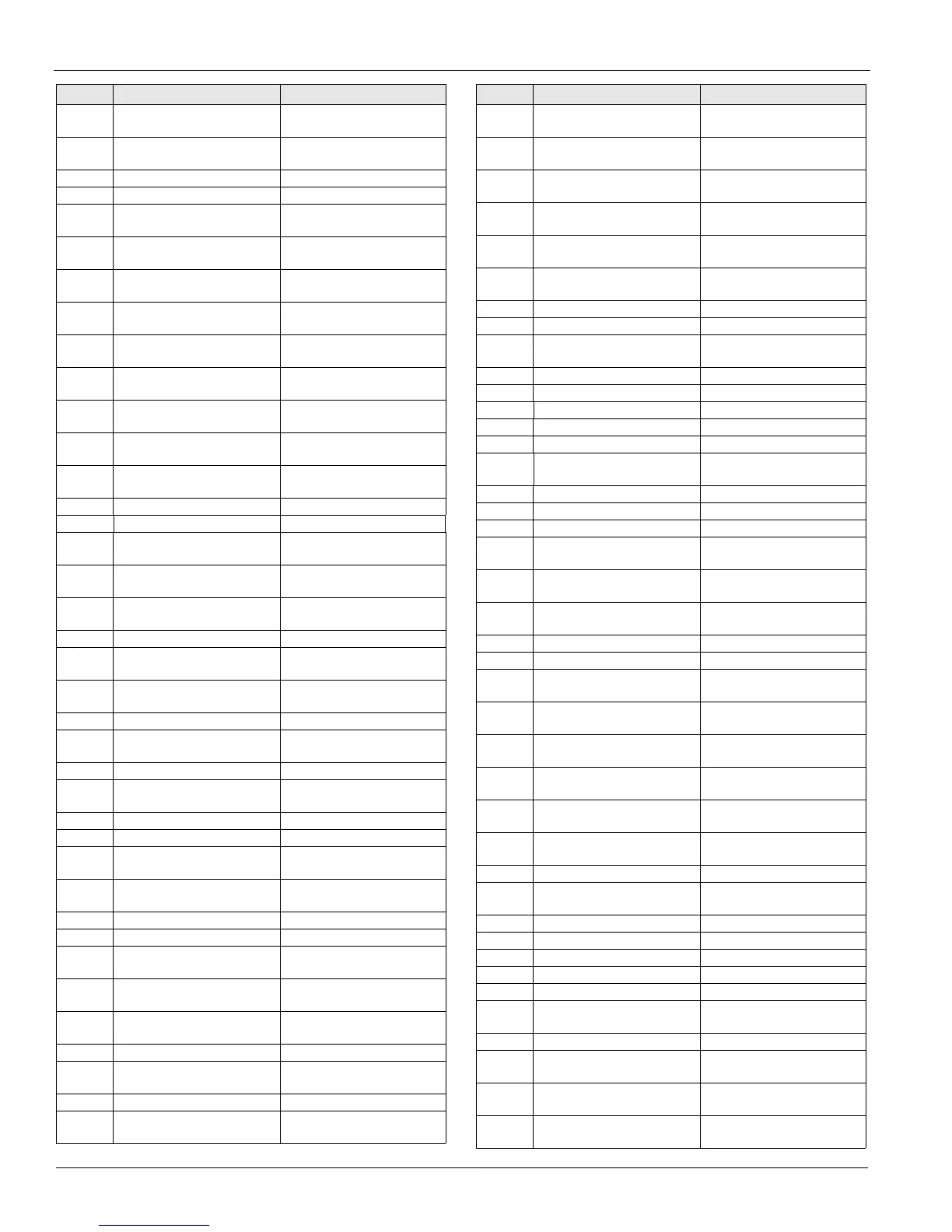
Wiring Diagrams
M41–50 Contactor, electric heat (bot.
bank)
Electric heat box
M60 Contactor, energy recovery
wheel
Main control box
MCB Microprocessor circuit board Main control box
MJ Mechanical Jumper All control boxes
MMP1–8 Manual motor protector, com-
pressors
Main/cond. control box
MMP10 Manual motor protector, sup-
ply fan
Main control box
MMP11–
18
Manual motor protector, cond.
fans, ckt#1
Main/cond. control box
MMP20 Manual motor protector, return
fan
Main control box
MMP21–
28
Manual motor protector, cond.
fans, ckt#2
Main/cond. control box
MMP30 Manual motor protector, invrtr.
bypass, sup. fan
Inverter bypass box
MMP40 Manual motor protector, invrtr.
bypass, ret. fan
Inverter bypass box
MMP51,
52, 53
Manual motor protector, ex-
haust fan(s)
Prop exhaust box
MMP60 Manual motor protector, ener-
gy recovery wheel
Main control box
MP1–6 Motor protector, compr.#1-6 On compressors
OAE Outside air enthalpy sensor Economizer section
OAT Outside air temperature sen-
sor
Economizer section
PB1, 2 Power block, power distribu-
tion
Main control box
PB3 Power block, power distribu-
tion, electric heat
Electric heat box
PB9, 10 Power block, supply fan Junction box, split unit
PB11, 12 Power block, power distribu-
tion
Main control box
PB19, 20 Power block, return/exhaust
fan
Junction box, split unit
PC5 Pressure control, clogged filter Pre filter section
PC6 Pressure control, clogged final
filter
Final filter section
PC7 Pressure control, proof airflow Supply fan section
PC8 Pressure control, minimum
airflow
Coil section, cool
PM1 Phone modem Main control box
PVM1, 2 Phase voltage monitor Main control box
R20 Relay, Heat, gas/ steam/ hot
water
Gas heat/main cont. box
R21, 22 Relay, heat, gas (hi-turn
down)
Gas heat box
R23 Relay, heat, gas & electric Gas/electric heat box
R24 Relay, heat alarm, gas Main control box
R25 Relay, heat, gas, start supply
fan inverter
Main control box
R26 Relay, isol/exh. dampers,
open/close
Main control box
R28 Relay, isolation damper, safe-
ty
Main control box
R29 Relay, remote fire alarm Main control box
R30 Relay, cool valve with face by-
pass
Main control box
R45 Relay, UV lights Main control box
R46, 47 Relay, supply fan inverter,
incr/decr
Main control box
ID Description Standard location
R48, 49 Relay, return fan inverter, incr/
decr
Main control box
R58,59 Relay, heat wheel inverter,
incr/decr
Main control box
R60 Relay, energy recovery wheel,
enable
Main control box
R61 Relay, smoke detector, dis-
charge air
Main control box
R62, 63,
65
Relay, use on specials Main control box
R66 Relay, smoke detector, return
air
Main control box
R67 Relay, supply fan, enable Main control box
R68 Relay, return fan, enable Main control box
R69 Relay, Inv. bypass VAV box in-
terlock
Main control box
R70–79 Relay, use on specials Main control box
RAE Return air enthalpy sensor Return section
RAT Return air temperature sensor Return section
REC1 Receptacle, main box Main control box
REC3 Receptacle, field power, 115V Discharge bulkhead
REC10–
23
Receptacle, cabinet sections Cabinet sections
S1 Switch, system on/off Main control box
S3 Switch, furnace on/off Gas heat box
S4 Switch, inverter bypass, on/ off Main control box
S7 Switch, local on/auto/off to
controller
Main control box
S10–23 Switches, cabinet section
lights
Cabinet sections
S40–45 Switches, door interlock, UV
lights
Cabinet sections
SD1 Smoke detector, supply Discharge section
SD2 Smoke detector, return Return section
SPS1, 2 Static pressure sensors, duct/
building
Main control box
SR1-3 Sequencing relays, electric
heat
Electric heat box
T1 Transformer, main control
(line/115 V (ac)
Main control box
T2 Transformer, control input
(115/24 V (ac)
Main control box
T3 Transformer, control output
(115/24 V (ac)
Main control box
T4 Transformer, exh. damper ac-
tuator (115/12 V (dc)
Main control box
T5 Transformer, electric heat Electric heat box
T6 Transformer, dew point con-
troller (115/24 V (ac)
Main control box
T9 Transformer, refrig. circuit 24V Main control box
TB1 Terminal block, internal Main control box
TB2 Terminal block, field Main control box
TB3 Terminal blocks, factory Main control box
TB4 Terminal block, RFS, field Main control box
TB7 Terminal block, 115V conve-
nience outlet, field
Main control box
TB11 Terminal block, heat Heat control box
TB25, 26,
27, 28
Terminal block, split unit junc-
tion box
Junction box, split unit
TD5–8 Time delay, part winding, com-
pr #1 - 4
Main control box
TD10 Time delay, hi turn down burn-
er
Gas heat box
ID Description Standard location