16 McQuay IM 937
Electrical Data
Supply Power Wiring
1 Units require three-phase power supply.
2 Allowable voltage tolerances:
a 60 Hertz
Nameplate 208 V: Min. 187 V, Max. 229 V
Nameplate 230 V: Min. 207 V, Max. 253 V
Nameplate 460 V: Min. 414 V, Max. 506 V
Nameplate 575 V: Min. 518 V, Max. 632 V
b 50 Hertz
Nameplate 400 V: Min. 342 V, Max. 418 V
3 Power lead wire sizing:
a For units with cooling capability (all concurrent loads)
with or without hot water heating and circuits with
motor loads only:
MCA = 1.25 (largest motor RLA or FLA) + other loads
+ 2 amps
b For units with cooling capability and nonconcurrent
electric heat capability:
In the cooling mode, the loads are composed of supply
fan motor and compressors. In heating mode, the
loads are composed of supply fan motor and electric
heater. The MCA is calculated for unit running in
either mode; the highest value obtained is used for the
MCA.
– For unit in cooling mode:
MCA = 1.25 (largest RLA or FLA) + other loads + 2
amps
– For unit in heating mode, below 50 kW
MCA = 1.25 (electric heat FLA + fan FLA) + 2 amps
– For unit in heating mode, above 50 kW
MCA = 1.25 (SAF amps) + (electric heat) + 2 amps
4 Size wires in accordance with Table 310-16 of the National
Electrical Code.
5 Size wires for a maximum of 3% voltage drop.
Lug Sizes
Note: Use copper wire only.
Control Center
All electrical controls are enclosed in a central control center
located at the front of the unit. High voltage components
include:
• Fan motor contactor, M30/M10
• Fan motor protector, MMP9, MMP10, MMP30
• Fan motor circuit breaker, CB10
• Compressor contactors, M1–M6
• Compressor protector, MMP1–MMP6
• Electric heat contactors, M11–M16
• Transformer, T1, T2, T3
• Disconnect switch, DS1–DS2
• Power block, PB1–PB2
If the optional disconnect switch is provided, the switch handle
is visible and accessible without removing any safety or access
panels.
Low voltage components include:
• MicroTech III
®
main control board, MCB
• MicroTech III
®
expansion modules
• Duct static pressure sensor, SPS1
• Optional 2nd duct static pressure sensor, SPS2
• Optional BACnet
®
/IP communication module
• Optional BACnet MS/TP communication module
• Optional L
ONWORKS
®
communication module
Located on the face of the unit is the interactive MicroTech III
keypad/display, unit switch, system indicator light and power
indicator.
Note: IM 919 has additional layouts of the control center.
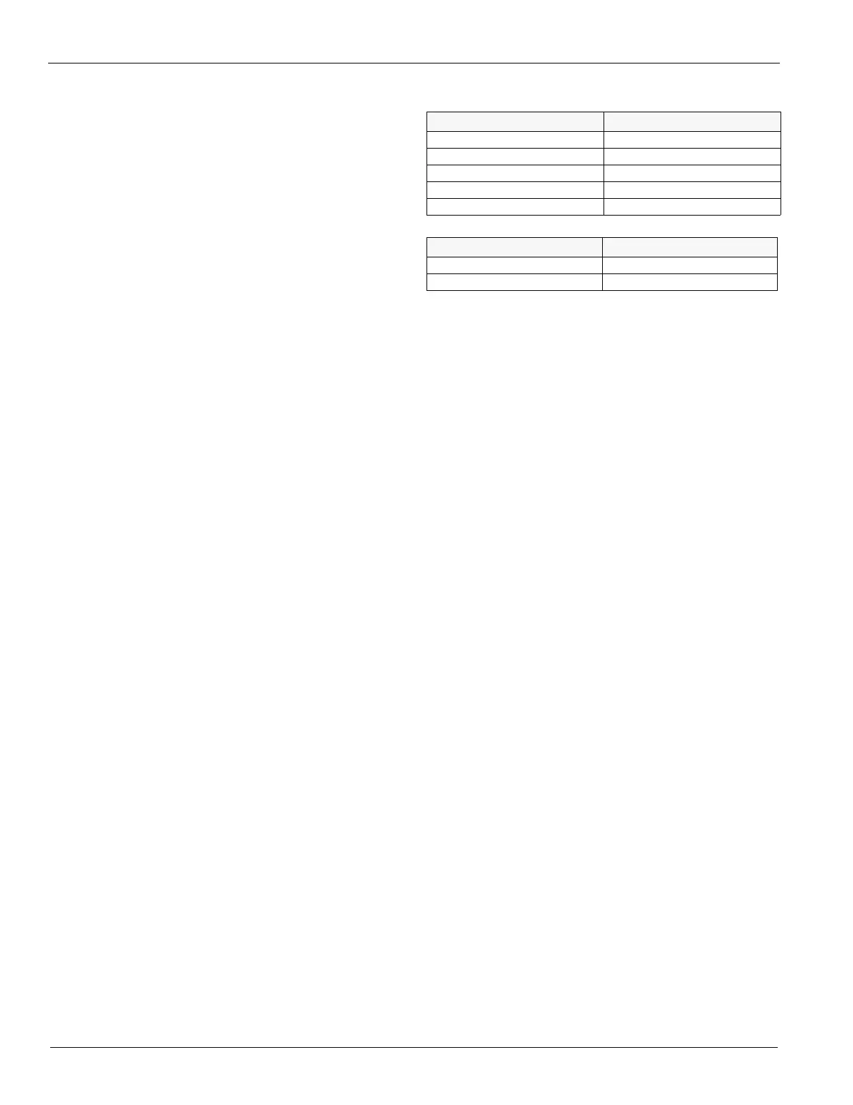
Table 10: Lug Sizes for Single Disconnect
DIsconnect size (amps) Lug size
100 #14-1/0
150 #8-3/0
250 3/0-350 MCM
400 (2) #4-250 MCM
600 (3) 3/0-500 MCM
Table 11: Lug Sizes for Power Block
Power block size (amps) Lug size
420 #2-600 MCM
760 (2) #4-500 MCM
 Loading...