4 McQuay IM 937
Installation
Installation
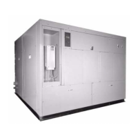
Handling
Units ship with a protective covering that should remain in
place while the unit is being moved to its final location.
Units are provided with lifting lugs for rigging with a crane. If
units are lifted by crane, use slings or cable to protect against
chaffing damage and use spreader bars across the top of the
cabinet to prevent any structural damage to the frame.
The unit base frame accepts dollies or Johnson bars for
transporting. Place dollies at both ends of the chassis or at one
end and use a Johnson bar at the other end for maneuvering.
Protect floor surfaces when equipment is moved across
finished flooring. Use plywood sheeting to protect surfaces
and distribute weight loading.
Vibration Isolators
All units are provided with 1" neoprene isolation pads, shipped
separately. Install pads beneath the unit, locating at each corner
and the center of each base channel. For units provided with
more than six isolator pads, evenly space the additional pads
under the front and rear base channels.
Setting Factory-Supplied Plenum
If the unit is provided with a factory plenum for field
mounting, use a forklift, slings, or other suitable lifting means.
Foam rubber gasketing is provided around the perimeter of the
unit top. Carefully set the plenum. Attach with mounting
hardware provided with the plenum.
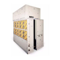
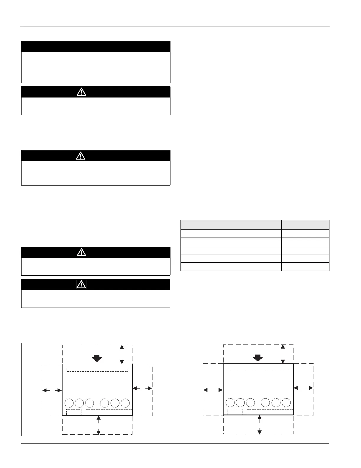
Location/Service Access
To facilitate installation and provide service, and maintenance
access, follow the recommended clearances in Table 1.
Minimum clearances required by local, state, or federal codes
such as the NEC take precedence over those listed below.
Clearance is required to allow room for side filter access,
mechanical cleaning of the condenser tubes and economizer
coil, access to expansion valves and other control components,
and to allow for possible fan shaft or compressor removal.
Figure 2: Recommended Service and Maintenance Clearance
IMPORTANT
Only qualified personnel familiar with local codes and
regulations and experienced with this type of equipment
should perform installation and maintenance.
Check for
concealed damage as soon as possible.
CAUTION
Sharp edges and coil surfaces can cause personal injury.
Wear protective gear and avoid contact.
WARNING
Never allow any part of the unit to fall during unloading or
moving as this can cause equipment damage, severe
personal injury, or death.
CAUTION
Do not attempt to install dollies in the center of the unit.
Units can become unstable and tip over, causing injury
CAUTION
Do not move units in an upended position.
Internal components may tear away, causing injury.
Table 1: Recommended Clearances
Location Clearance length
Unit front 42"
Unit rear 24"
Motor location, right side 36"
Piping location, left side or right side 36"
Side without motor or piping 24"
Airflow
24"
42"
Evaporator Coil
Compressors
36"
24"
or
36"
1
AFD
Electrical Panel
Left
Side
Right
Side
Front
Back
Condenser
Cleanout
3 5 6 4 2
Motor
Airflow
24"
42"
Evaporator coil
Compressors
36"
24"
or
36"
1
AFD
Electrical panel
Left
side
Right
side
Front
Back
Condenser
cleanout
3 5 2 4 6
Motor
Independent
circuits
Dual circuits
 Loading...