8 McQuay IM 937
Installation
Duct Connections
Supply Air
To connect supply ductwork directly to the unit, first mount a
duct collar at the fan outlet, avoiding the mounting screws
located around the perimeter of the fan discharge opening. See
Figure 11. Fan discharge opening sizes are indicated on the
unit dimensional drawings. McQuay recommends a canvas
type connecting collar.
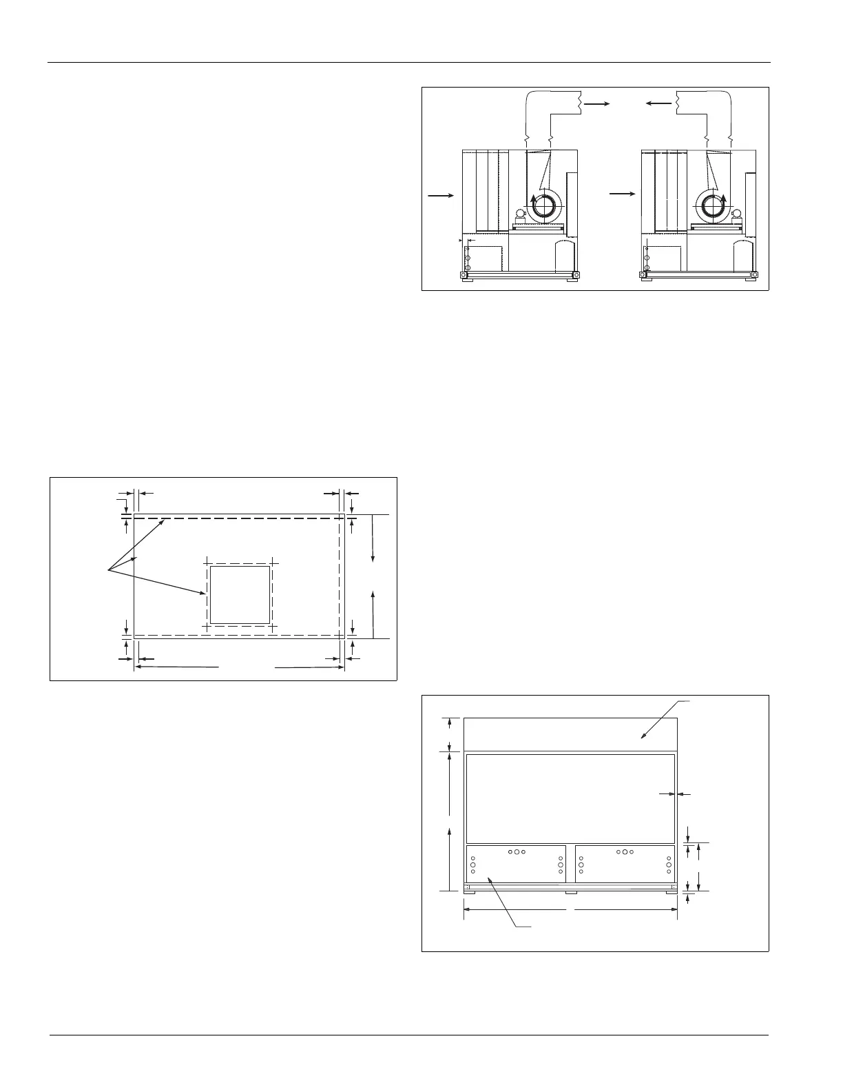
Install ductwork as shown in Figure 12. Duct take-offs that are
installed opposite to the direction of fan rotation result in an
associated system effect loss and reduced fan performance.
If a field-fabricated plenum is used, again, correctly orient duct
take-off locations to the rotation of the fan to minimize system
losses. Refer to unit dimensional drawings and Figure 11 for
plenum mounting size requirements. Canvas type connectors
are recommended at the duct connection to the plenum.
Units are also available with a factory-provided discharge
plenum. Supply duct connections to the plenum opening(s)
should include a canvas-type connector. Plenum opening sizes
and locations are indicated on the job submittal drawing.
Figure 11: Unit Top Detail
If a field-fabricated plenum is used, again correctly orient duct
take-off locations to the rotation of the fan to minimize system
losses. Refer to unit dimensional drawings and Figure 11. for
plenum mounting size requirements. Use canvas type
connectors at the duct connection to the plenum.
Units are also available with a factory-provided discharge
plenum. Supply duct connections to the plenum opening(s)
should include a canvas-type connector. Plenum opening sizes
and locations are indicated on the job submittal drawing.
Figure 12: Discharge Duct Configurations
Return Air
Return air to the unit can be ducted or free, as follows.
Ducted return
Attach return ductwork to the 2" flange around the perimeter
of the unit’s return air opening. Refer to Figure 13. Use a
canvas-type duct connecting collar. All ductwork connected to
the unit must be of adequate size and construction for the
application. Also use a canvas-type connector where the duct
penetrates the machine room wall(s). This helps prevent
vibration generated by air movement in the duct from being
transmitted out to the occupied spaces.
Note: Do not obstruct the unit access panel located below the
return opening.
Free return
Use the mechanical equipment room as a return plenum with
no hard connection at the unit.
Note: Some building codes do not allow using the mechanical
room as a return plenum. Check applicable local codes
for each installation.
Figure 13: Back Elevation
Filters are removable from the rear of the unit or through a side filter access
door located on the piping connection side. Length increases by
approximately 3 1/2" for piping connections with water economizer option.
Mechanical access panel(s) in the back of the unit start 2" below the return
duct opening. Do not obstruct the access panel(s). All dimensions are ±0.25".
Fan
discharge
opening
Centerline of
sheet metal
screws
Unit length
Unit
depth
1.7" (typ)
1.7" (typ)
Filter Section
Economizer
Evaporator
Heater
Electrical panel
Filter Section
Economizer
Evaporator
Heater
Electrical Panel
M
2.0”
2.0” Typical
29”
D
B
K x L
Return Air Opening
Mechanical
Access
(See Notes)
(Optional)
Multi-Directional
Plenum
1” Neoprene
Isolation Pads,
Shipped Separately
 Loading...