McQuay IM 937 31
Control Panel Components
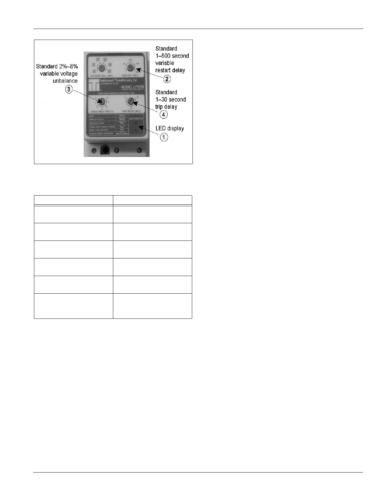
Figure 32: Phase Voltage Monitor
There are two LEDs on the face of the PVM (“1” in Figure 32)
to indicate the following:
Other features:
• Standard 2% to 8% variable voltage unbalance (“3” in
Figure 32).
• Standard 1 to 500 second variable restart delay (“2” in
Figure 32).
• Standard 1 to 30 second trip delay (“4” in Figure 32) (except
loss of phase, which trips at 1 second non-adjustable).
High Pressure Switches
The high pressure switch (HP1-HP6) is a single pole pressure
activated device that opens on a pressure rise. When the switch
opens, it de-energizes the compressor circuit, shutting down
the compressor. The MicroTech III controller displays an
alarm condition. Once the cause of the fault is identified and
corrected, manually reset the unit through the MicroTech III
keypad/display interface. The control is attached to a Shrader
fitting and is located at the compressor. To check the control,
shut off water flow to the condensers and observe the cutout
point on a high pressure gauge. The high pressure control
should open at 360 psig and close at 300 psig. After testing the
high pressure control, check the pressure relief device for
leaks.
Low Pressure Switches
The low pressure switch (LP1-LP6) is a single pole, pressure
activated device that closes on a pressure rise. It senses
evaporator pressure and is factory set to close at 60 psig and
open at 35 psig. Compressor operation is not allowed until the
switch closes. The low pressure switch is an automatic reset
control. If the condition occurs on any one compressor three
times in a 24-hour period, the alarm has to be reset manually
through the MicroTech III keypad/display interface to restart
the compressor. The low pressure switch is attached to a
Shrader fitting and is located at the compressor.
Compressor Motor Protector
All compressors are thermally protected. The solid state
protection device (MP1-MP6) is located in the compressor
junction box. Whenever the protection system opens, the
compressor shut downs for 30 minutes.
The solid state protection device is used on the following:
• Dual circuits—13, 15 hp
• Independent circuits—13, 15, 20 hp
The in-line protection control automatically resets when the
alarm condition is removed and the time delay is satisfied.
The in-line protection device is used on the following:
• Dual circuits—6, 7, 8, 9, 10 hp
• Independent circuits—6, 10 hp
Table 12: LED Indication
Status LED Indicator
Normal operation, no faults,
relay energized
Green LED - steady on
Loss of input phase (relay de-
energized)
Red LED - flash twice, off,
flash twice, off, etc.
Voltage unbalance (relay de-
energized)
Red LED - flash twice, off,
flash twice, off, etc.
High or low voltage (relay
de-energized)
Red LED - steady on
Phase reversal (relay de-
energized)
Red LED - pulse on, off, on,
off, etc.
Restart delay (fault cleared,
PVM pending restart, relay
de-energized)
Green LED - pulse on, off,
on, off, etc.
 Loading...