6 McQuay IM 937
Installation
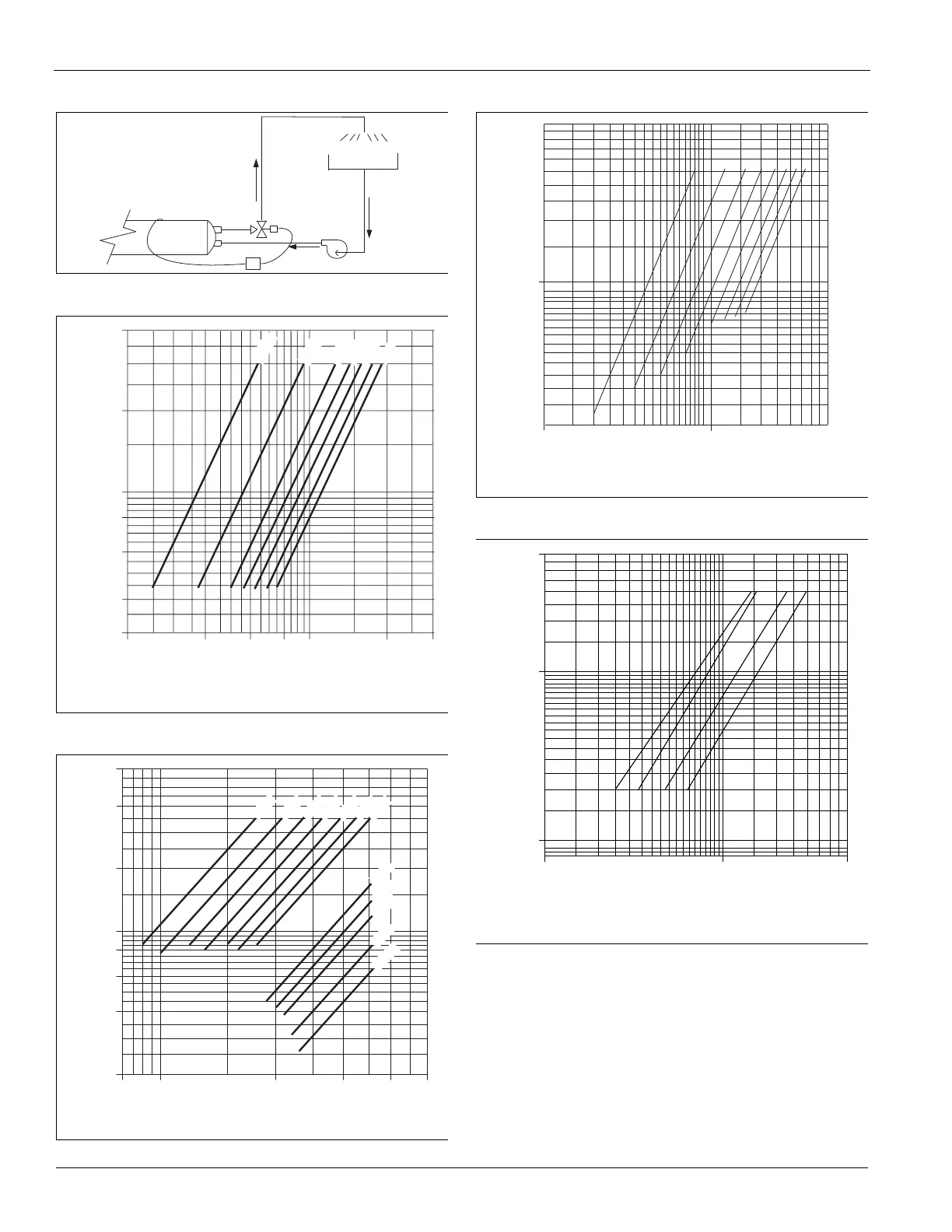
Figure 3: Condenser Regulating Valve (Refrigerant
Pressure Controlled)
Figure 4: Condenser Water Pressure Drop, SWP 018 to 040,
Independent Circuit
Figure 5: Condenser Water Pressure Drop, SWP 045 to 105,
Independent Circuit
Figure 6: Condenser Water Pressure Drop, SWP 018 to 095,
Dual Circuit
Figure 7: Economizer Water Pressure Drop, SWP 018 to
105
Condenser
Cooling
tower
P
40
20
10
8
6
4
3
20
40
60 80
100
200 300
Condenser Flow Rate (gpm)
Pressure Drop (ft H
2
O)
12 HP
18 HP
24 HP
28 HP
32 HP
3
6 HP
40 HP
HP = total unit compressor horsepower
60
40
20
10
8
6
4
2
80 100
200 300
400 500
Condenser Flow Rate (gpm)
Pressure Drop (ft H
2
O)
40HP
46HP
56HP
60HP
70HP
80HP
78HP
84HP
90HP
105HP
120HP
52HP
HP = total unit compressor horsepower
Condenser Flow Rate (gpm)
Pressure Drop (ft H
2
O)
60
10
40
20
6
8
4
2
10 100 500
12 HP
16 HP
24–32 HP
36–32h HP
46HP
52HP
56HP
60 HP
HP = total unit compressor horsepower
10 100 500
1
10
50
018–028
035–040
045–095
105
P16
Condenser Flow Rate (gpm)
Pressure Drop (ft H O)
2
Note: 1. Includes coil, control valves and interconnecting piping.
2. Add this P to condenser P to obtain unit P for pump selection
 Loading...