Do you have a question about the Mea Hawk and is the answer not in the manual?
Advises on Lock Out and Tag Out procedures for electrical hazards.
Warns about pinch points and recommends PPE for mechanical work.
Emphasizes caution for electrical work and use of qualified technicians.
Advises on working in areas free of ignitable concentrations.
Warns about compressed springs and the need for decompression before work.
Highlights risks associated with pressurized accumulators and de-pressurization.
Advises using Lock Out/Tag Out procedures with manual handwheel assembly.
Information about the manufacturer MEA Inc.
Details for contacting MEA Inc. for support and service.
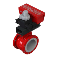
Overview of the Hawk actuator as a high-performance, rugged electro-hydraulic unit.
Stroke lengths and thrust output specifications for the linear actuator.
Rotation and torque output specifications for the rotary actuator.
Details optional features available for the Hawk actuator.
Describes the three levels of manual operation available for the actuator.
Explains how the actuator fails to a specific position on loss of power or signal.
Details the Safe Seat feature for protecting valve seating surfaces.
Lists key technical specifications for the actuator's construction and control.
Specifies approved hazardous area classifications for the actuator and enclosure.
Details the operating temperature ranges for the actuator and control enclosure.
Details specifications for thermal jackets and heat tracing for low-temperature operation.
Lists special tools required for installation and maintenance procedures.
Describes packaging methods for parcel and freight shipments.
Advises on inspecting products upon receipt and handling potential shipping damage.
Provides recommendations for storing MEA products in a controlled environment.
Details the pre-filled state of the Hawk actuator and inspection after unpacking.
Explains the electro-hydraulic system using a bi-directional gear pump and servo motor.
Describes the linear actuator's operation with a double-acting cylinder and HPS.
Explains the rotary actuator's operation using cylinders, rack, and pinion linkage.
Discusses the use of secondary motor/pump units for high thrust/torque or speed.
Provides a breakdown of the Hawk actuator model number configuration options.
Explains the different operational modes of the actuator.
Covers settings for adjusting actuator speed and response characteristics.
Sets the point where the actuator switches from fast to slow speed for fine-positioning.
Configures the slower speed used for fine-positioning actuator movements.
Sets the faster speed used for large position changes.
Sets the actuator speed for Manual and Setup mode operations.
Defines the duration before a fault alarm is sent if the actuator doesn't reach position.
Tunes speed and response for units with multiple motor/pump configurations.
Determines minimum deviation to activate secondary motor/pump for larger movements.
Sets the point for deactivating secondary motor/pump for final positioning.
Details calibration of stroke endpoints and control signal inputs for 4-20 mA signals.
Explains configuration of actuator behavior on loss of signal or power.
Confirms all electrical connections are secure and verified prior to powering up.
Outlines the procedure for grounding the Control Enclosure per local codes.
Emphasizes proper alignment to prevent damage to the actuator or valve/damper.
Provides steps for aligning a linear actuator in a vertical position.
Details the procedure for aligning a rotary actuator to a valve.
Confirms key mechanical installation checks prior to commissioning.
Explains how to check the hydraulic fluid level using the indicator inside the HPS enclosure.
Step-by-step guide for filling the HPS with hydraulic fluid and purging air.
Describes the function and components of the accumulator system for energy storage.
Provides instructions for draining hydraulic fluid and nitrogen from the accumulator system.
Details the process for filling the accumulator and reservoir with fluid and nitrogen.
Explains the Safe Seat system's mechanism for accurate seat load control.
Guides on adjusting the Safe Seat trigger point and pressure switch setpoint.
Lists general safety precautions for installation and maintenance.
Steps to safely release stored energy from accumulator/reservoir systems.
Procedure for safely releasing stored energy from the Safe Seat system.
Recommends quarterly visual inspections to identify mechanical issues.
Lists maintenance tasks to be performed at five-year intervals.
Outlines extensive maintenance required for long-term operation at ten-year intervals.
| Brand | Mea |
|---|---|
| Model | Hawk |
| Category | Controller |
| Language | English |