MEA INC
2600 American Lane | Elk Grove Village, IL 60007 | USA
T +1 847 766 9040 | F +1 847 350 1951
COMPLETE CONTROL
www.meaincorporated.com
MEA Incorporated | Hawk Actuator Instruction and Operation Manual
02/2018
17
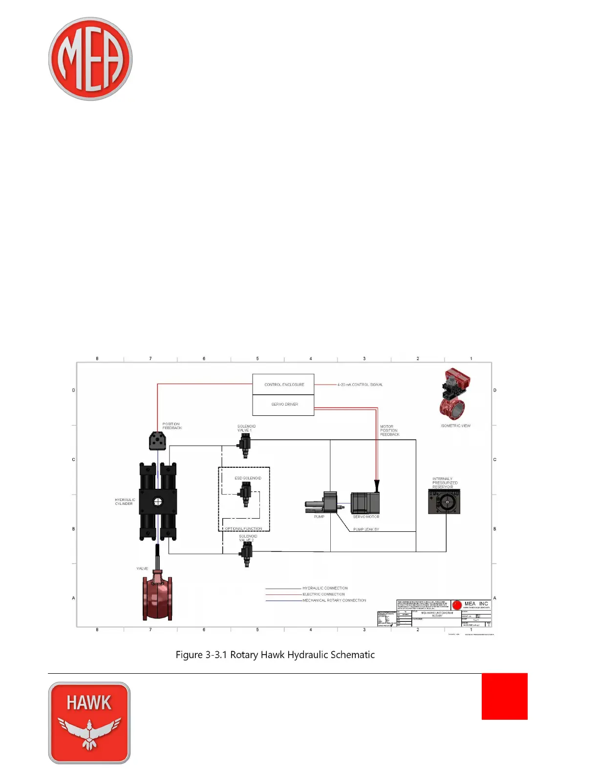
3-3 Rotary Actuator
The rotary version of the Hawk actuator consists, depending on required torque output, of either one or
two double-acting, equal displacement cylinders which in combination with a rack and pinion linkage and
pressurized fluid from the HPS, creates rotary movement of the driven device. In Control mode, the
actuator receives a desired position signal from the DCS. This signal is compared to the current position
signal provided by the actuator’s position feedback. The difference between the desired position and
current position is the deviation. If this deviation exceeds the user defined deadband the servo driver
begins the process of moving the actuator by first energizing the motor, which in turn spins the pump.
For a brief period, less than 80 ms, the pump builds pressure in the system before the solenoids are
energized. Once sufficient system pressure is generated, the solenoids open and the hydraulic fluid
moves the cylinders and the driven device.
Ultimately, the actuator will rotate the driven device in the direction that will decrease the deviation to 0%
± the deadband. Once reaching this position the servo motor and solenoids will de-energize and the
actuator will remain in place until the next deviation occurs.
Figure 3-3.1 Rotary Hawk Hydraulic Schematic