"2033ES / 2633ES" Service & Parts Manual - ANSI Specifications October 2008
Page 5-19
2217
none
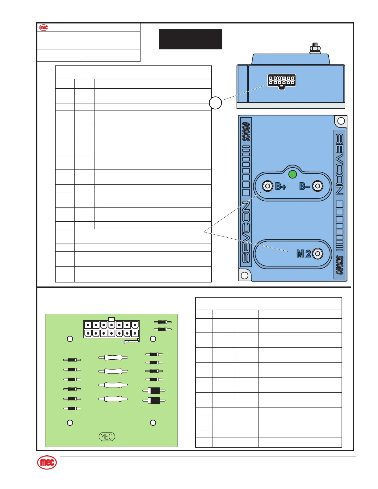
Controller Plug Pin Identicication
ES Models : all
Model: / Serial #
Publication Art #:Reference Art #:
_
_
REFER TO
ELECTRIC SCHEMATIC
1
7
6
12
J5 Pin Identification
PIN # WIRE # FUNCTION
1 22 B+ power input
(power up)
2 17 Lift, Drive or Steer functions requested
(functions requiring motor)
3 18 Steer Requested
(adds additional motor speed for steer)
4 3 Enable signal input
5 21 Speed cut-back
(24 Volts = full speed, 0 Volts = creep speed)
6 16 Motor Start Relay signal
(GROUND signal to activate Motor Start Relay)
7 41 Lift Valve B-
(provides GROUND signal to Lift Valve)
8 none none
9 14 Accelerator reference signal
(3.6 Volts to Potentiometer)
10 none none
11 none none
12 none none
Terminal Identification
POST FUNCTION
B+ Battery Positive Cable from 200 AMP Fuse
B- Negative Battery Cable and GROUND wire (15) connection
M2 Motor Ground
(Pulse-Width Modulated [PWM] variable speed control)
PWM
Motor Controller
J5
J1
14
71
8
D9
D10
D11
D15
TB1
D8
D7
D14
D5
D13
R2
R1
R3
R4
D3
D12
D4
D1
D2
8601
J1 Plug Pin Identification
PIN # WIRE # SIGNAL FUNCTION
1 10 INPUT Drive Reverse
2 11 INPUT Drive Forward
3 19 OUTPUT Brake, Decel Valve signal
4 8 INPUT Steer Left
5 18 OUTPUT Steer signal to Sevcon
6 5 INPUT Down signal
7 20 OUTPUT Signal to Motion Alarm(s)
(optional)
8 17 OUTPUT Sevcon & Hour Meter
(motor function requested)
9 15 INPUT Battery Negative
10 7 INPUT Steer Right
11 4 INPUT Lift Up
12 2 INPUT Limit Switch
(24V = platform down)
13 3 OUTPUT Enable, from lower Lift switch
14 21 OUTPUT To Sevcon (for speed cutback)
Circuit Board